SHOULD NOT be in contact with any part of the structure. Check Installation
local codes covering zoning, noise, platforms, etc..
Avoid locating next to fresh air intakes, vent or bedroom windows.
Noise may carry into the openings and disturb people inside.
Avoid installations under roof overhangs without guttering. Water
draining from the roof onto the unit could produce excessive
noise, and may cause ice to build up on coil or fan.
Placement of the unit should be in a well drained area or the unit
MUST be supported high enough so runoff will not enter the unit.
Do not locate unit where heat, lint or exhaust fumes wil! be
discharged on unit (as from dryer vents.)
Clearances
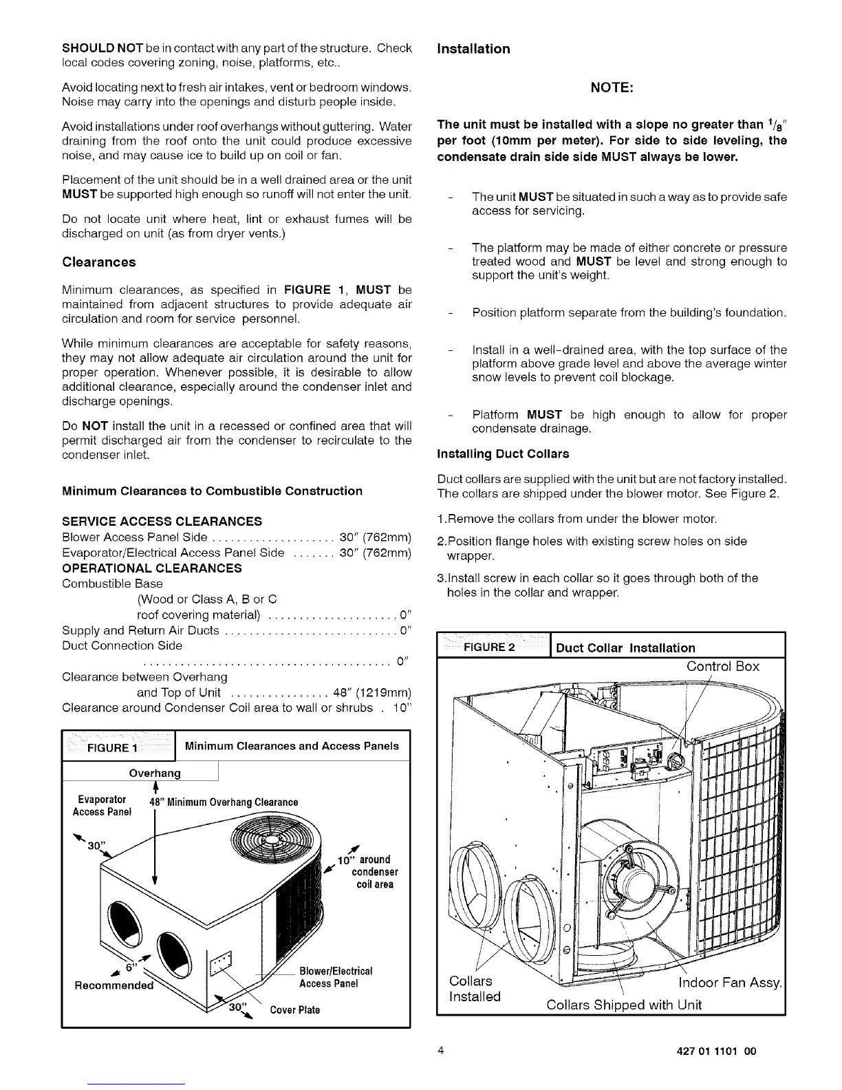
Minimum clearances, as specified in FIGURE 1, MUST be
maintained from adjacent structures to provide adequate air
circulation and room for service personnel.
While minimum clearances are acceptable for safety reasons,
they may not allow adequate air circulation around the unit for
proper operation. Whenever possible, it is desirable to allow
additional clearance, especially around the condenser inlet and
discharge openings.
Do NOT install the unit in a recessed or confined area that will
permit discharged air from the condenser to recirculate to the
condenser inlet.
Minimum Clearances to Combustible Construction
SERVICE ACCESS CLEARANCES
Blower Access Panel Side .................... 30" (762mm)
Evaporator/Electrical Access Panel Side ....... 30" (762mm)
OPERATIONAL CLEARANCES
Combustible Base
(Wood or Class A, B or C
roof covering material) ..................... 0"
Supply and Return Air Ducts ............................ 0"
Duct Connection Side
........................................ 0 sl
Clearance between Overhang
and Top of Unit ................ 48" (1219mm)
Clearance around Condenser Coil area to wall or shrubs . 10"
FIGURE i Minimum Clearances and Access Panels
Overhang
Evaporator 48" MinimumOverhangClearance
AccessPanel
10" around
f condenser
coilarea
BlowedElectrical
AccessPanel
CoverPlate
NOTE:
The unit must be installed with a slope no greater than 1/8"
per foot (10mm per meter). For side to side leveling, the
condensate drain side side MUST always be lower.
The unit MUST be situated in such a way as to provide safe
access for servicing.
The platform may be made of either concrete or pressure
treated wood and MUST be level and strong enough to
support the unit's weight.
Position platform separate from the building's foundation.
install in a well-drained area, with the top surface of the
platform above grade level and above the average winter
snow levels to prevent coil blockage.
Platform MUST be high enough to allow for proper
condensate drainage.
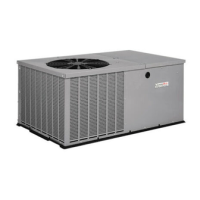
Installing Duct Collars
Duct collars are supplied with the unit but are not factory installed.
The collars are shipped under the blower motor. See Figure 2.
1.Remove the collars from under the blower motor.
2.Position flange holes with existing screw holes on side
wrapper.
3.Install screw in each collar so it goes through both of the
holes in the collar and wrapper.
FIGURE2 I Duct Collar Installation
Control Box
Collars
Installed
Indoor Fan Assy.
Collars Shipped with Unit
4 427 01 1101 00