Do you have a question about the ICP PHX330000K00A1 and is the answer not in the manual?
Details dimensions for the "B" Chassis heat pump units, including specific measurements for various components.
Provides dimensions for roof curbs designed for "B" Chassis units, specifying measurements for different configurations.
Details dimensions for the "C" Chassis heat pump units, including specific measurements for various components.
Provides dimensions for roof curbs designed for "C" Chassis units, specifying measurements for different configurations.
Highlights critical safety warnings, including electrical shock and fire hazards, emphasizing qualified personnel.
Explains the safety-alert symbol and signal words (DANGER, WARNING, CAUTION, NOTE) used in the manual.
Provides essential safety guidelines for unit installation, including positioning, static pressure, and filter checks.
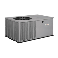
Brief overview of the PHX3 unit as a self-contained electric heat pump designed for outdoor installation.
Guidance on selecting an appropriate location for the unit, considering sound and clearance requirements.
Specifies minimum clearances required around the unit for safe operation and adequate air circulation.
Important notice regarding unit leveling requirements for proper operation and drainage.
Requirements for installing the unit on a ground-level platform, ensuring stability and drainage.
Guidelines for rooftop installation, including structural support and platform requirements.
Instructions for safely hoisting the unit, emphasizing the use of spreader bars and secure rigging.
Steps for converting the unit for downflow air discharge configuration.
Details on the condensate drain connection, including size and location.
Cautionary note regarding improper electrical connections potentially reducing equipment lifespan.
Requirement for a field-supplied, waterproof disconnect switch for the unit's electrical service.
Instructions for ensuring a permanent, uninterrupted electrical ground connection for safety.
Guidance on making line voltage connections within the unit's control box, referencing wiring diagrams.
Instructions for connecting the thermostat and low voltage wiring, emphasizing correct location and wiring.
Recommendations for ductwork velocity limits to ensure proper airflow and system efficiency.
Requirements for insulating outdoor ductwork with fiberglass wrap and a weatherproof vapor barrier.
Guidelines for connecting supply and return plenums to the unit, ensuring proper sealing.
Details the necessity of using filters and lists recommended sizes based on face velocities for optimal performance.
Information on blower speed taps and corresponding wiring for heating and cooling stages.
Procedure for setting blower motor speeds when the same speed is required for heating and low-stage cooling.
Pre-start checks including blower speed, air filters, and access panels before powering the unit.
Description of the cooling cycle operation, including staged cooling and fan control.
Description of the heating cycle operation, including staged heating and auxiliary heat control.
Explanation of the compressor recycle delay timer function to prevent reverse rotation.
Details on continuous indoor fan operation and its effect on airflow settings.
Explanation of the defrost mode, including delay settings, sequence, and termination.
Detailed sequence of operation during defrost mode, including fan, reversing valve, and heat control.
Routine monthly checks including air filters, condenser coil, and condensate drain for optimal performance.
Specific monthly checks recommended during the cooling season, focusing on condenser coil and drain.
Comprehensive annual inspection tasks, including fan motors, blower access, and motor replacement.
Critical safety warnings for rigging, emphasizing panel placement, spreader bars, and secure shackles.
Table detailing maximum length, width, height, and weight for small and large cabinet rigging.
Schematic diagram illustrating electrical connections for 2 to 5 ton units, including component layout.
 Loading...