ADS-HRR(SR)-MFT1-DS-IG-EN maestro.idatalink.com
FORD EDGE WITH MYFORD TOUCH 20112013
Automotive Data Solutions Inc. © 2023
4
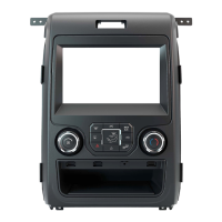
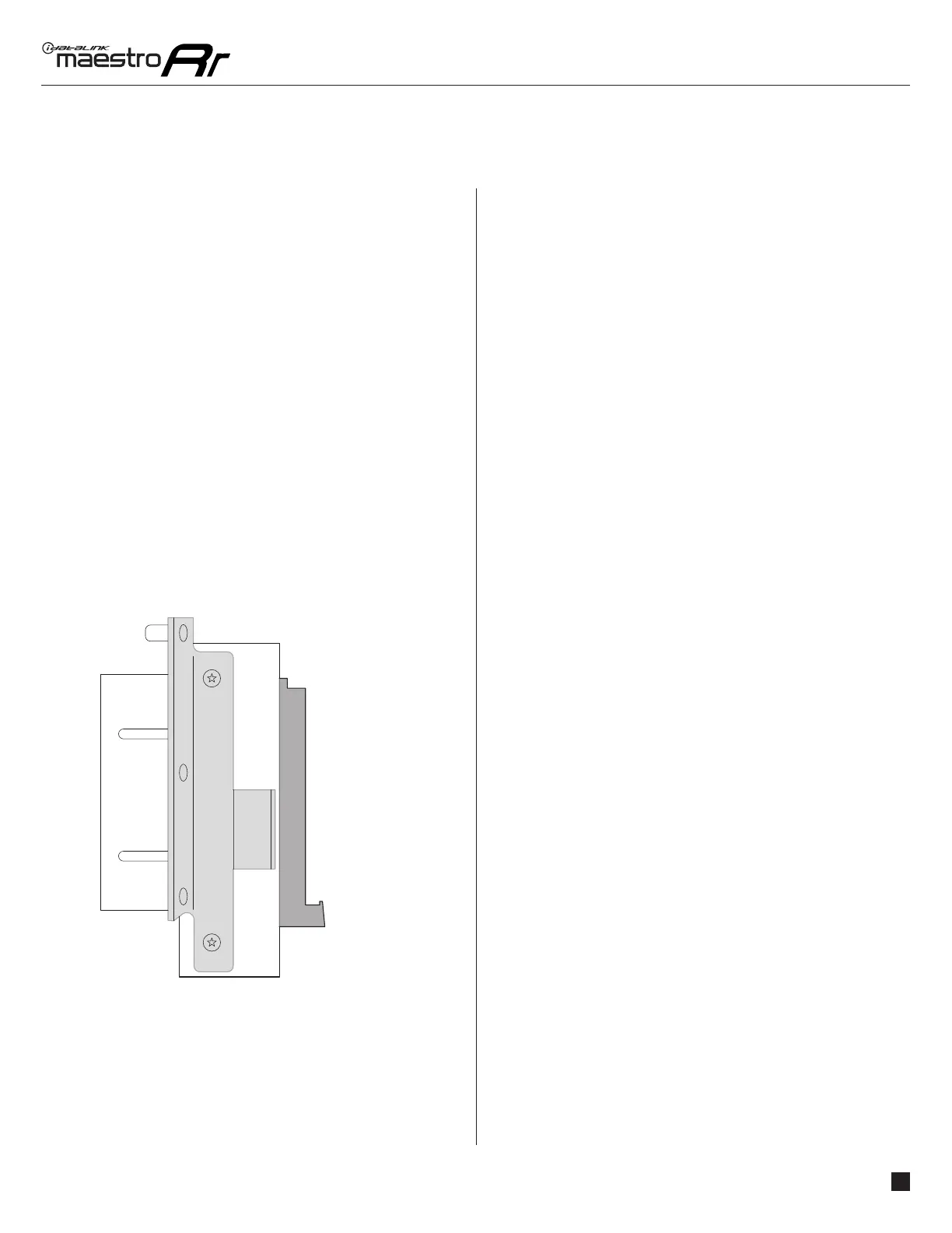
Fig. 2.0
A B C
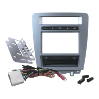
DASH KIT ASSEMBLY
1. Attach the brackets supplied with the MFT1 to the
aftermarket radio (use set #1 or #2, see previous page).
2. Remove the mounting brackets from the OEM screen and
attach them to MFT1 brackets (Example: Fig. 2.0).
3. Clip MFT1 panel on to the front of MFT1 brackets.
Media port adapter
4. Remove OEM Media port and connect MFT1 media port
adapter to aftermarket radio. If OEM media port is larger
than MFT1 media port, insert the supplied adapter plate,
then install MFT1 media port.
(Side view)
A: MFT1 bracket
B: OEM radio bracket
C: Aftermarket radio
MAKE CONNECTIONS (refer to wiring diagram)
1. If using head unit adapter (sold separately), connect HRR-
MFT1 harness to adapter and skip to step 2.
• Unbox the aftermarket radio and locate its main harness.
• Cut and remove the black 20 pin connector from the
HRR-MFT1 T-harness and connect the wires, shown in the
wiring diagram, from aftermarket radio main harness to
the HRR-MI1 T-harness and match the wire functions.
Note: only connect purple/white wire to radio reverse input
or module damage will occur.
2. Determine if the vehicle has a factory amplifi er.
If the vehicle DOES NOT have a factory amplifi er:
• Plug the female 4-pin BLACK connector to the male BLACK
connector of your HRR-MFT1 T-harness.
• Plug the female 4-pin WHITE connector to the male WHITE
connector of your HRR-MFT1 T-harness.
If the vehicle DOES have a factory amplifi er:
• Leave the 4-pin BLACK connector unplugged.
• Plug the C cable to the 4-pin WHITE connector.
• Connect gray and white RCAs into the aftermarket radio.
3. Assemble HRR-MFT1 harness as shown in the wiring
diagram, using A, B and D harnesses.
• Connect the MFT1 T-harness to the factory radio harness.
4. Connect all harnesses to the Maestro RR module.
5. Plug the harnesses into the aftermarket radio.
• Plug the data cable to the data port of the aftermarket
radio.
• Insert the audio cable into the iDatalink 3.5mm audio jack
of the aftermarket radio (labeled iDatalink. If there is no
iDatalink audio input, connect to AUX).
• Plug the backup camera RCA into the aftermarket radio (if
applicable).
Note: When using a Pioneer radio, please ensure that there
is nothing plugged into the W/R port of the radio.
Insert the radio and MFT1 kit in the dash, then test your
installation.
1
INSTALLATION INSTRUCTIONS P2 /2
 Loading...