52
Installation and Servicing
SECTION 3 - SERVICING
1. Refer to Section 3.8.
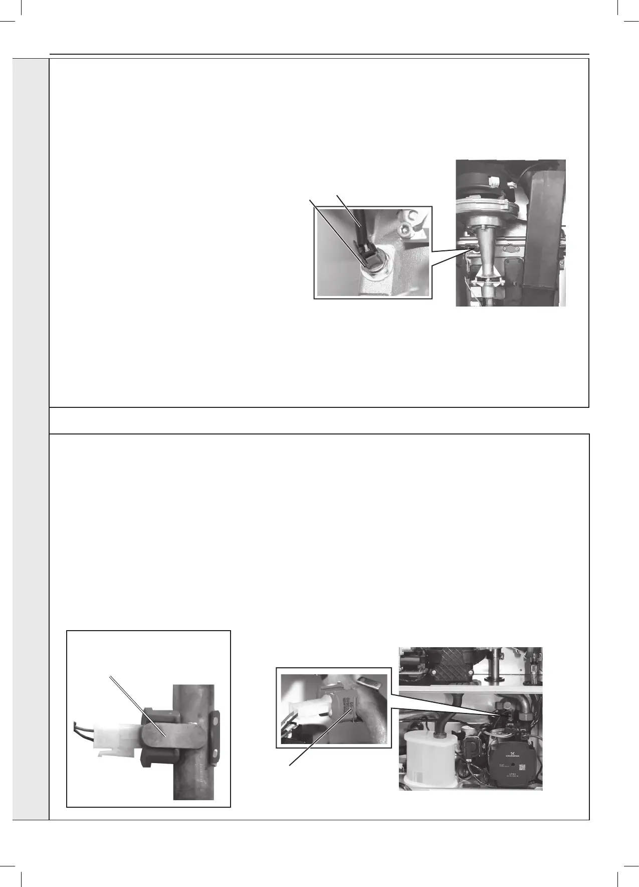
2. Unclip the return thermistor from the return pipe and
withdraw it from the boiler.
3. Disconnect the electrical lead from the thermistor.
4. Reconnect the electrical lead to the new thermistor and
reassemble in reverse order, ensuring that the thermistor
is securely tted to the pipe on the thermistor locator tab
as shown.
5. Check that the boiler operates in both DHW & CH Mode.
3.29 FLOW THERMISTOR
Thermistor Locator Tab
(with thermistor tted)
3.30 RETURN THERMISTOR REPLACEMENT REPLACEMENT
1. Refer to Section 3.8.
2. Drain down the boiler. Refer to Section 3.19.
3. Unplug the electrical lead.
4. Unscrew the thermistor (to facilitate removal a
13mm socket spanner should be used).
5. Fit the new thermistor using the sealing
washer provided.
6. Reassemble in the reverse order.
7. Rell the boiler.
8.
Check the operation of the boiler.
Refer to
Sections 2.24 & 2.25.
SERVICING



 To Next Page