16
INSTALLATION
ESPRIT 2 - Installation and Servicing
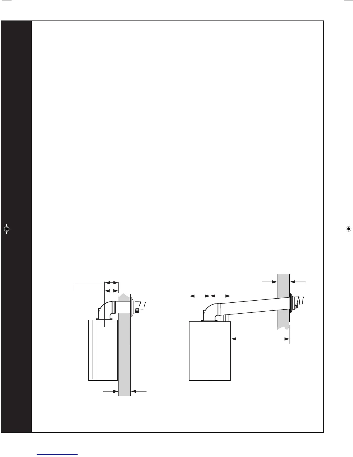
FLUE OUTLET
Wall Thickness X
160 mm
160 + S = 193mm
nm8943
FLUE KITS
Pack B - supplied as standard
Pack D - optional extension kit for side flue or rear flue outlet
SCREW KIT - Optional kit for mechanical fixing of flue joints
Finishing Kit - Supplied as an optional extra
Refer to 'Flue Extension Ducts'
IMPORTANT. The boiler MUST be installed in a vertical position
Dimension X - Wall thickness.
Dimension L - Wall thickness plus boiler spacing.
Dimension S - Stand-off frame depth = 33mm
12
DETERMINING THE FLUE LENGTH AND FLUE PACKS REQUIRED
Note.
MAXIMUM FLUE LENGTHS:
24 & 30 - 6M (HORIZONTAL FLUE)
35 - 3M (HORIZONTAL FLUE)
24, 30 & 35 - 7.5M (ROOF FLUE)
24, 30 & 35 - 5M PRIMARY AND 17M SECONDARY IS A TYPICAL MAX. FLUE LENGTH.
(For alternative details refer to Powered Vertical Instructions)
90
O
ELBOW KIT 60/100 (EQUIVALENT FLUE LENGTH RESISTANCE = 1M)
45
O
ELBOW KIT 60/100 (EQUIVALENT FLUE LENGTH RESISTANCE = 0.6M)
MINIMUM HORIZONTAL FLUE LENGTHS - TELESCOPIC TERMINAL = 370MM
(Centre Line of turret to outside of wall terminal) - ONE PIECE TERMINAL = 285MM
195mm
195mm
Wall Thickness X
Side flue length L
SIDE FLUE
REAR FLUE
continued . . . . .
206091-1.pmd 26/05/2010, 16:0816