41
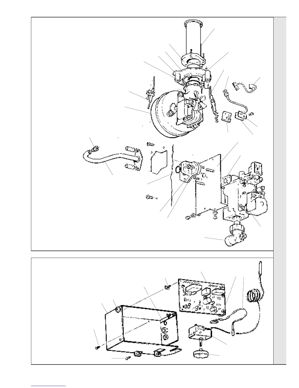
Minimiser - Installation
LEGEND
1. Control box.
2. Control box retaining screw.
3. 'Burner on' neon.
4. Boiler control thermostat.
5. Thermostat knob.
6. Cable entries.
7. Control box mounting
pivots.
8. Printed circuit board
mounting posts (4).
9. Printed circuit board no. 37.
78
BURNER ASSEMBLY - Exploded view
SERVICING
SERVICING
LEGEND
1. Burner
2. Spark electrode
3. Burner mounting
flange
4. Detection electrode
5. O ring
6. Gasket
7. Gasket
8. O ring (not shown)
9. Fan
10. Burner injector
11. Gas injection pipe
12. O ring
13. Manifold block
14. Gasket
15. Gas valve mounting
bracket
16. Gasket
17. Gas valve
18. Gas service cock
19. Gasket
11
18
1
2
7
79
CONTROL BOX ASSEMBLY - Exploded view
5
4
6
9
1
7
3
4
9
10
12
16
17
13
20. Burner pressure sensing pipe
21. O ring
22. Fan pressure sensing pipe
23. Sensing pipe clamping plate
8
8
3
8
8
20
22
15
5
6
2
21
14
19
23
 Loading...