45
Installation and Servicing
Section 3 - Servicing
SERVICING
Refer to Section
3.8
Refer to Section
3.20
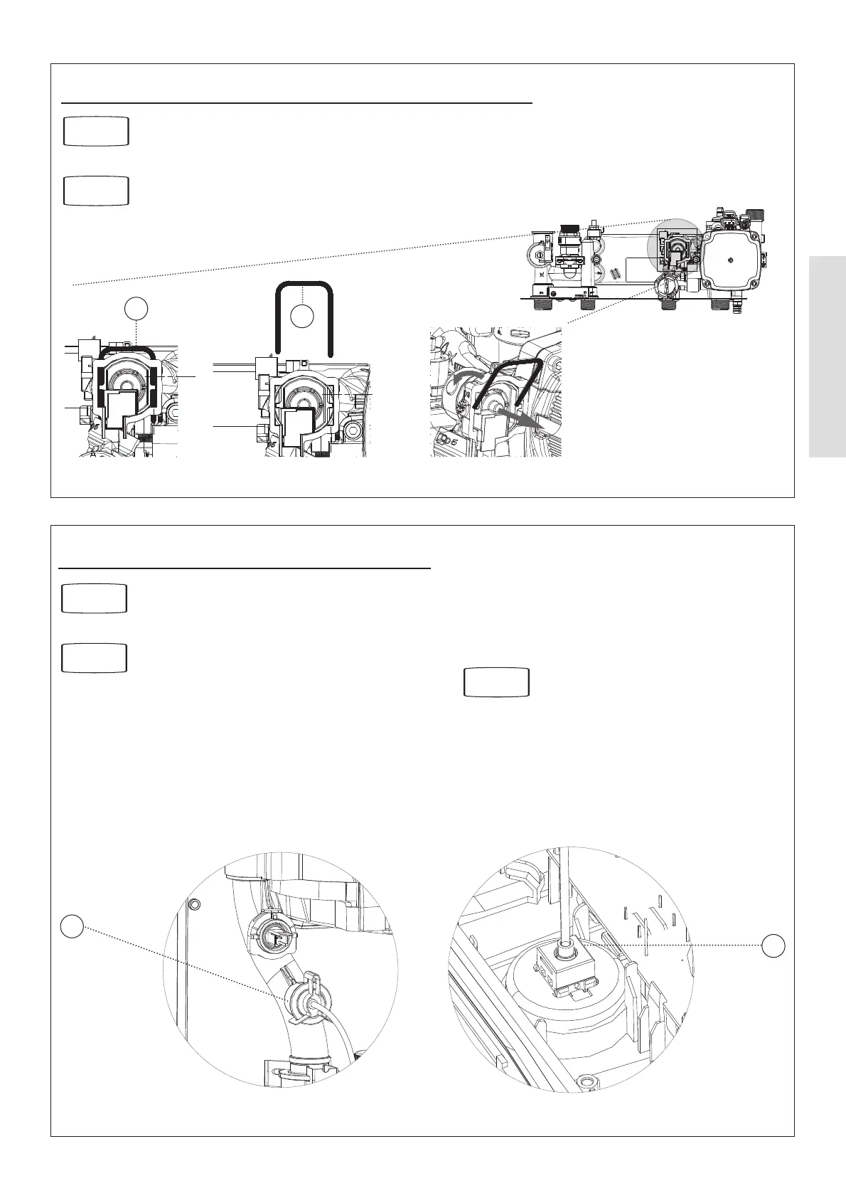
3.20 DHW FLOW TURBINE SENSOR REPLACEMENT
1. Drain the DHW system.
2. Pull o the electrical connection.
3. Using a suitable tool, lift and remove the retaining clip.
4. Use the clip to ease the turbine sensor from its housing.
5. Reassemble.
3
4
3.21 PRESSURE GAUGE REPLACEMENT
1. Drain the heating system.
2. Remove the boiler front (see section 2.3), lower the
control panel and remove the control box cover.
3. Ensuring there is no pressure in the system unclip the
C clip from the ow pipe port and remove the capillary
connection together with ‘O’ ring.
4.
Releasing the two retaining clips on the pressure gauge
ease the pressure gauge through the front of the control
panel.
5. Fit the new pressure gauge from the front of the lower
control panel ensuring correct orientation. Locate push t
connection into ow pipe ensuring ‘O’ ring in place and
secure with the C clip.
6. Rell the boiler.
3
5
Refer to Section
3.2
Refer to Section
3.3
Refer to Section
2.17