7Installation and Servicing
Section 1 - General
24 kW 30 kW 35 kW
Gas Supply 2H - G20 - 20 mbar
Gas Supply Connection 15 mm copper compression
Injector Size mm 4.15 4.65 4.9
Inlet Connection Cold Water 15 mm copper compression
Outlet Connection Cold Hot Water 15 mm copper compression
Flow Connection Central Heating 22 mm copper compression
Return Connection Central Heating 22 mm copper compression
Flue Terminal Diameter mm 100
Average Flue Temp-Mass Flow Rate DHW 63ºC - 11g/s 68ºC - 13g/s 73ºC - 15g/s
CO
2
Content (± 0.7) Max. DHW 9.2% 9.3% 9.7%
Min. CH 8.5% 8.5% 8.8%
Maximum Working Pressure (Sealed Systems) bar (psi) 2.5 (36.3)
Maximum Domestic Hot Water Inlet Pressure bar (psi) [kPa] 10.0 (145) [1000]
Minimum Domestic Hot Water Inlet Pressure* bar (psi) [kPa] 0.8(11.6)(80) 1.3(18.9) (130) 1.3(18.9)**(130)
Minimum DHW Inlet Pressure to Operate at 0.6 bar System Pressure
All Model Sizes 0.5 bar
Electrical Supply 230 V ~ 50 Hz
Power Consumption W 96 91 110
Fuse Rating External : 3 A Internal : T4A HRC L250 V
Water Content Central Heating litre (gal) 1.2 (0.26)
Domestic Hot Water litre (gal) 1.0 (0.22)
Packaged Weight kg 32.8 33 33
Lift Weight kg 28.5 28.6 28.6
Boiler Casing Size Height mm 700
Width mm 395
Depth mm 278
Maximum DHW Input: 24 kW 30 kW 35 kW
Nett CV kW 24.3 30.4 35.4
Gross CV kW 27 33.7 39.3
Gas Consumption m
3
/h 2.512 3.135 3.657
ft
3
/h 89 111 129
Maximum DHW Output kW 24.2 30.3 35.3
DHW Flow Rate l/min 9.9 12.4 14.5
At 35ºC Temp. Rise gpm 2.2 2.8 3.2
DHW Specic Rate l/min 11.5 14.5 16.9
gpm
2.5 3.2 3.7
Boiler Page
Make and model .........................................................9
Appliance serial no. on data badge .................Front Cover
SEDBUK No. % ..........................................................8
Controls
Time and temperature control to heating .................29
Time and temperature control to hot water .............29
Heating zone valves ................................................n/a
TRV’s........................................................................12
Auto bypass ....................................................................12
Boiler interlock ..........................................................12
For all boilers
Flushing to BS.7593 .................................................15
Inhibitor ...........................................................................15
Central heating mode
Heat input
...................................................to be calculated
For assistance call Technical Helpline
01482 498663
Page
Burner operating pressure ......................................n/a
Central heating ow temp. ...........measure and record
Central heating return temp. ........measure and record
For combination boilers only
Scale reducer ........................................................... 15
Hot water mode
Heat input ............................................ to be calculated
Max. operating burner pressure .............................. n/a
Max. operating water pressure ........ measure & record
Cold water inlet temp ...................... measure & record
Hot water outlet temp. ..................... measure & record
Water ow rate at max. setting ........ measure & record
For condensing boilers only
Condensate drain ................................................ 25-26
For all boilers: Complete, sign & hand over to customer
For UK, to comply with Building Regulations Part L1 (Part 6 in Scotland) the boiler should be tted in accordance with the
manufacturer’s instructions. Self-certication that the boiler has been installed to comply with Building Regulations can be
demonstrated by completing and signing the Benchmark Commissioning Checklist.
Before installing this boiler, read the Code of Practice sheet at the rear of this book.
BENCHMARK COMMISSIONING CHECKLIST DETAILS
NOTE TO THE INSTALLER:
COMPLETE THE BENCHMARK
COMMISSIONING CHECKLIST AND LEAVE THESE
INSTRUCTIONS WITH APPLIANCE
Natural Gas Only
Destination Country: GB
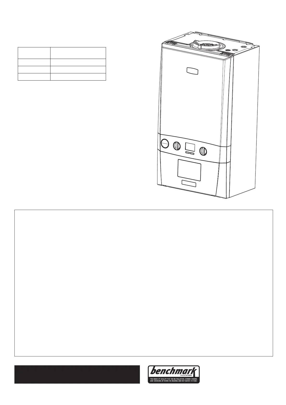
LOGIC COMBI
2
C
BOILER SIZE
kW
G.C. Applicance No
(Benchmark No.)
24
47-349-93
30
47-349-94
35
47-349-95
 Loading...