20 CHECK-VALVE REPLACEMENT
25
1. Demount the mixer body from the wall, as detailed in section 15, follow steps 1 to 4.
2. Locate the sealing washers (with integral strainers) from inside the mixer’s inlet bores & keep
them in a safe location.
3. The check valves are housed inside the retaining inserts within the inlet bores. Look closely at
the rear of the mixer body.
4. Note: circlips hold the check valves in position. Using circlip pliers, squeeze the circlip & lift it away
from the bore.
5. Gently pull out the check valves: inspect & clean or replace if necessary. Observe the ow direction
arrow on the body of the check valve as shown above. Ret the circlips.
6. To ret the mixer to the wall reverse this procedure (remember to t the sealing washers).
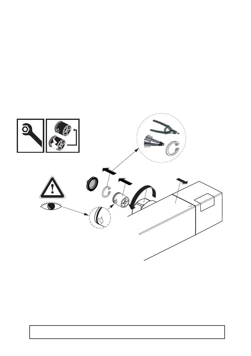
1. Remove the ow control handle (right side) as detailed in section 16. Remove also the drive bush
tted to the spindle of the ow cartridge. Note: the square end cap can remain inside the mixer body.
2. Slide o the stop ring.
3. Using a 17mm spanner or socket, undo the ow cartridge. The cartridge should now slide out of the
mixer’s bore.
4. If necessary, replace the cartridge with a new one. Alternatively, if the cartridge is functioning correctly,
clean it thoroughly & reuse it.
5. With the cartridge located back in the mixer bore, screw the cartridge into the mixer body by
hand & then tighten with a spanner or socket. Ideally torque to 16Nm min to 18Nm max.
6. Ret the stop ring as illustrated above. Align the marked arrow on the stop ring to the front top corner
of the mixer body or use the marker on the square end cap as guidance.
7. Rotate the cartridge spindle fully clockwise until it stops.
8. Reverse the sequence to ret the drive bush & handle. Check & adjust the o position as shown
in section 8. Ensure correct alignment of the handle as detailed in section 16.
IMPORTANT: Although the check valves can be replaced, they must not be removed
completely. Do not operate the mixer without BOTH the check valves correctly tted.
Observe flow
direction
Strainer
washers
 Loading...