Page 7
CALIBRATION
Calibration Preparation
1. Turn on the calibrator, allow calibrator to warm up. Perform calibration at
23±2°C (73.4°F ±3.5°F) at relative humidity of < 70%. Temperature stabilization should be
reached after 30 minutes.
2. Disconnect the test leads and turn the range switch to “OFF”.
3. Remove the screws holding the battery cover, one at the jaw, and the screw for the TightSight™
cover.
4. Remove the case bottom using care not to damage the leads of battery snap and spring
to the continuity beeper. (Beeper is attached to the bottom case cover.)
5. Using a calibrated meter ensure the battery measures a minimum of 7.5V DC.
If the battery measures under 7.5V DC, replace the battery (see Battery Replacement page 11).
Calibration Procedure
It is recommended that all IDEAL meters undergo the following calibration procedure on
an annual basis.
The class of calibrator or equipment should have an accuracy that exceeds, by an expectable ratio the
accuracy of this instrument.
V DC Calibration:
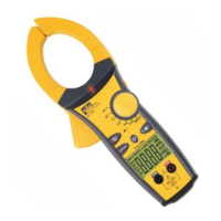
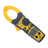
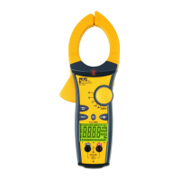
61-764 (Refer to Figure 1A), 61-766 (Refer to Figure 2A), 61-768 (Refer to Figure 3A)
1. Set the function / range to 6.6V DC.
2. Connect the calibrator to the V and COM inputs on the meter.
3. Output 3.900V DC.
Adjust VR1 (VR 1KΩ) until unit display reads 3.900. (61-764, 61-766)
Adjust VR2 (VR 1KΩ) until unit display reads 3.900. (61-768)
4. De-energize source and remove test leads
V AC Zero Calibration:
61-766 (Refer to Figure2A), 61-768 (Refer to Figure 3A)
1. Set the function /range to 750V AC.
2. Short the V and COM input on the meter.
3. Adjust VR3 (VR 220kΩ) until display reads 000.
4. De-energize source and remove test leads.
V AC Calibration:
61-766 (Refer to Figure 2A), 61-768 (Refer to Figure 3A)
1. Set the function/range to the 6.6V AC.
2. Connect the calibrator to the V and COM inputs on the meter.
3. Output 3.900VAC/60Hz.
Adjust VR2 (VR 1KΩ) until unit display reads 3.895 ± 1 digit. (61-766)
Adjust VR1 (VR 1KΩ) until unit display reads 3.895 ± 1 digit. (61-768)
4. De-energize source and remove test leads.
Form number TM61764-6-8 Rev 5 November 2007
 Loading...