3
• Never ground yourself when taking electrical measurements.
• Connect the black common lead to ground or neutral before applying the
red test lead to voltage. Disconnect the red test lead from the voltage first.
• Always work with a partner.
• When using the probes, keep fingers as far behind the probe tips as
possible.
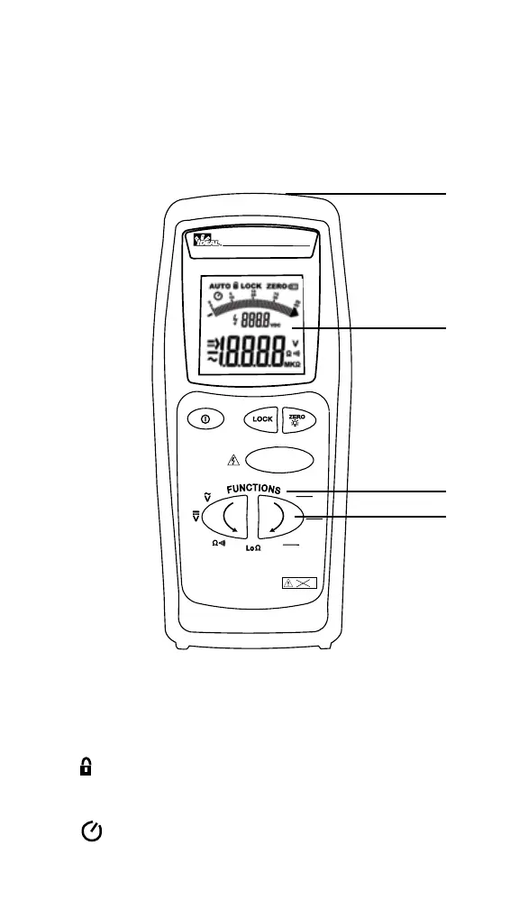
Instrument - Description
Feature Callouts
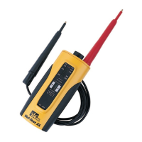
1. Inputs - for inserting test leads.
2. Display
• AUTO – indicates autoranging mode.
• LOCK – indicates a test lock for the next time the TEST
button is depressed.
• ZERO – indicates test leads have been nulled.
• – indicates auto power off (APO) occurs 15 minutes after
last button is depressed. To defeat APO, press the LOCK key.
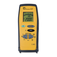
61-795
Digital Insulation Tester
1000V
Test
MΩ
500V
MΩ
250V
MΩ
>605V
1
2
3
4