24
Concord CXA/H - Installation and Servicing
SERVICING
40
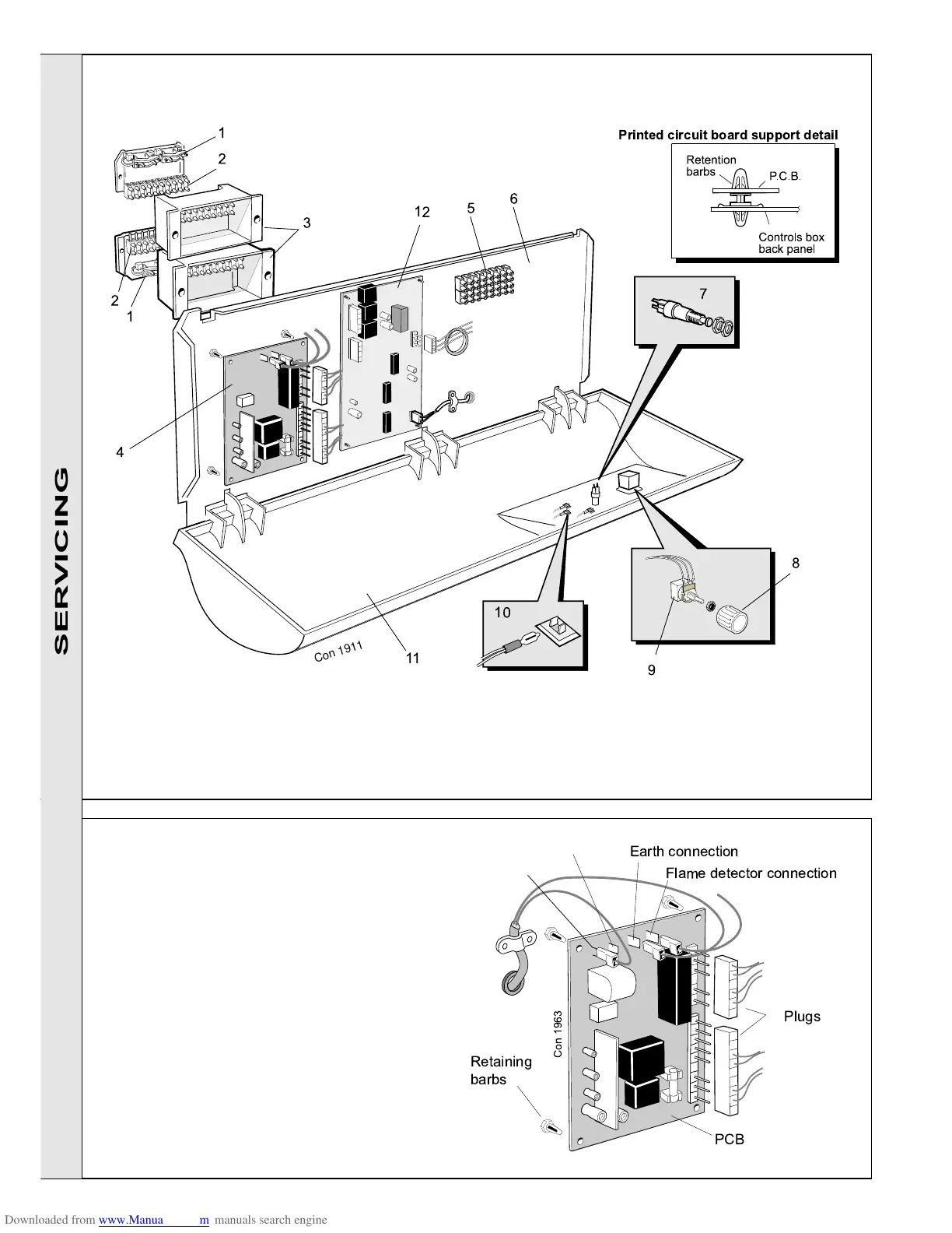
CONTROL BOX - Basic Boiler, Exploded View
LEGEND
1. Wiring clamp.
2. Connection box plug.
3. Connection box.
4. PCB S4561A1054
5. Terminal strip
6. Back panel
7. Lockout reset button
8. Thermostat knob
9. Potentiometer
10. Warning light lens
11. Controls box
12. PCB W4115A1020
41
PC BOARD NO. S4561B1054
1. Remove the lower front panel.
2. Undo the 2 screws securing the control box front
panel. Carefully lift it up and lower down.
3. Pull off the 2 plugs and 3 push-on connections from
the board. The board can now be removed by
squeezing in the retaining barbs.
4. Re-assemble in reverse order, ensuring that the
push-on connections are as follows (from left to right):
spark electrode, blank, earth, flame detector.
Printed circuit board support detail
11
1
2
3
12
5
8
9
C
o
n
1
9
1
1
1
2
10
4
6
7
Earth connection
Flame detector connection
PCB
Retaining
barbs
Con 1963
Plugs
SERVICING
 Loading...