31
Concord CXi - Installation
44
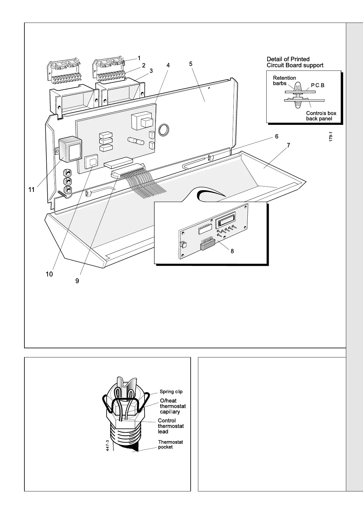
CONTROL BOX - Basic Boiler Exploded View
SERVICING
SERVICING
46
PC BOARD NO. 34
1. Remove the casing door panel.
2. Slacken the 2 screws securing the control box front
panel. Carefully lift it up and hinge forward.
3. Release the ribbon cable from PCB No. 34 by
pushing the retaining tabs sideways.
4. Release all plug connections from the board.
5. Remove the real time clock board (PCB No. RTC/
34) from PCB No. 34 by pulling gently forward.
6. Release PCB No. 34 from the 7 plastic mounting
pins and 2 screws and pull it forward.
7. Reassemble in reverse order.
45
CONTROL SENSOR
1. Lift off the casing top
panel.
2. Trace the sensor lead
to the pocket in the
flow header, remove
the spring clip and
remove the sensor
phial.
3. Unclip the sensor lead
from its clips on the
casing. Undo the
screws on the
connector box plug
and remove it.
4. Fit the new sensor and reassemble in reverse order.
9. Ribbon cable.
10. Printed circuit board No. RTC/34.
11. EMC filter.
12. Controls box fascia (not shown).
LEGEND
1. Wiring clamp.
2. Connection box plug.
3. Connection box.
4. Printed circuit board No. 34.
5. Back panel.
6. Hinge pin.
7. Controls box.
8. Printed circuit board No. 35.
 Loading...