6
Concord CXi - Installation
GENERAL
POSITION OF BOILER
Minimum clearances required from walls or
other fixed objects to allow for the free access
of combustion air are shown in Table 4 above.
Any combustible material adjacent to the
boiler and its flue system must be so placed or
shielded as to ensure that its temperature
does not exceed 65
0
C (150
0
F).
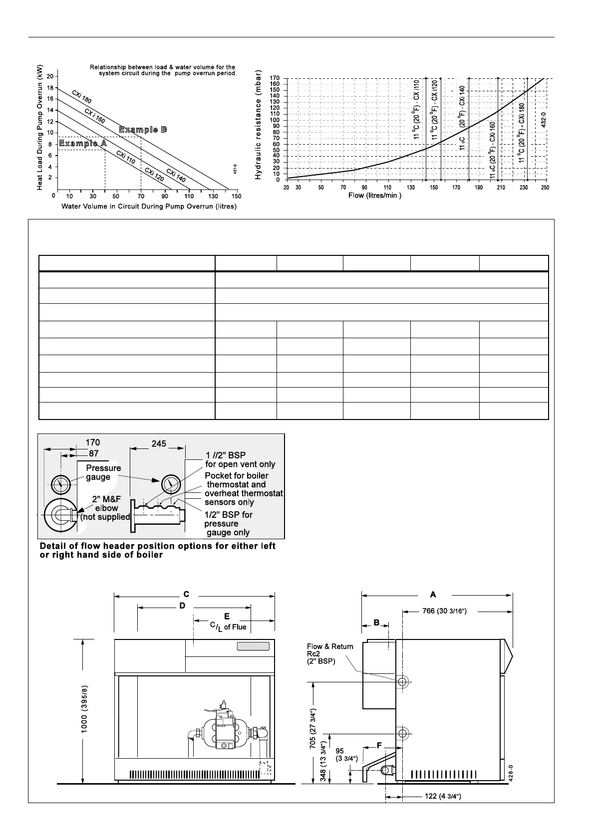
Graph 2 - Hydraulic Resistance
Boiler Size CXi 110 CXi 120 CXi 140 CXi 160 CXi 180
Front clearance mm (in) 750 (29
1/2)
Rear clearance mm (in) 200 (8)
Side clearance mm (in) 100 (4) - not including clearance for side fitted flow header
Dimension A mm (in) 1036 (40
3/4) 1036 (40 3/4) 1036 (40 3/4) 1086 (42 3/4) 1140 (45)
Dimension B mm (in) 175 (7) 175 (7) 175 (7) 197 (7
3/4) 250 (10)
Dimension C mm (in) 1107 (43
3/4) 1107 (43 3/4) 1230 (48 1/2) 1353 (53 1/4) 1476 (58 1/8)
Dimension D mm (in) 816 (32
1/8) 816 (32 1/8) 939 (37) 1062 (42 3/4) 1185 (46 5/8)
Dimension E mm (in) 553 (21
3/4) 553 (21 3/4) 615 (24 1/4) 676 (26 5/8) 738 (29)
Dimension F mm (in) 220 (8
5/8) 220 (8 5/8) 220 (8 5/8) 220 (8 5/8) 320 (12 1/2)
2
CLEARANCES & DIMENSIONS
Table 4
Graph 1 - Heat Load / Water Volume
 Loading...