TFC Group Ltd. Tel. + 44 (0) 01732 351 680
Tower House, Vale Rise Fax. +44(0) 01732 354 445
Tonbridge. kent TN9 1TB www.tfc-group.co.uk
5.
ignition or damage to any part of any building.
6. The air inlet/products outlet duct and the terminal of the
boiler MUST NOT be closer than 25mm (1”) to combustible
IMPORTANT. It is essential to ensure, in practice, that products
of combustion discharging from the terminal cannot re-enter the
building or buildings through any openings into the building such
as ventilators, windows, doors, or other sources of natural air
be immediately investigated and corrected following the guidance
provided in the current Gas Industry Unsafe Situation Procedure.
WATER CIRCULATION SYSTEM
IMPORTANT.
connection to any plastic piping.
and return pipework should be connected in 28mm pipe.
For the types of system and correct piping procedure see Frames
1, and 3 to 8.
The central heating system should be in accordance with BS.6798
and, in addition, for smallbore and microbore systems, BS.5449.
WATER TREATMENT - see Frame 9
The hot water storage cylinder MUST be of the indirect type and
should preferably be manufactured of copper.
Single feed, indirect cylinders are not recommended and MUST
NOT be used on sealed systems.
The appliances are NOT suitable for gravity central heating nor
are they suitable for the provision of gravity domestic hot water.
The hot water cylinder and ancillary pipework, not forming part of
the useful heating surface, should be lagged to prevent heat loss
and any possible freezing - particularly where pipes run through
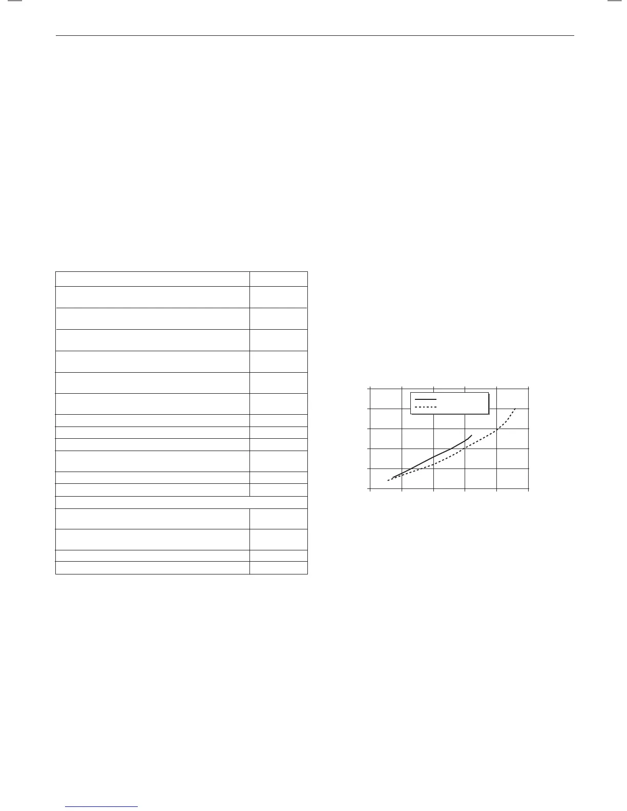
The boiler must be vented.
The hydraulic resistance of the boilers, at MAXIMUM OUTPUT, is
shown in Graph 1.
BOILER CONTROL INTERLOCKS
Ideal Boilers recommend that heating systems utilising full
thermostatic radiator valve control of temperature in individual
valve as stated in BS. 5449.
Central heating systems controls should be installed to ensure the
boiler is switched off when there is no demand for heating or hot
water.
When thermostatic radiator valves are used, the space heating
temperature control over a living / dining area or hallway having
should be achieved using a room thermostat, whilst other rooms
are individually controlled by thermostatic radiator valves.
However, if the system employs thermostatic radiator valves on all
radiators, or two port valves without end switches, then a bypass
Graph 1 - Water ow rate and pressure loss
TERMINAL
The terminal assembly can be adapted to accommodate various
wall thicknesses. Refer to Frame 19.
AIR SUPPLY
It is NOT necessary to have a purpose-provided air vent in the
room or internal space in which the boiler is installed. Neither
is it necessary to ventilate a cupboard or compartment in which
the boiler is installed, due to the low surface temperatures of the
boiler casing during operation; therefore the requirements of BS
Flue Terminal Positions
Min. Spacing*
1.
window, air vent or other ventilation opening. 300mm (12”)
2.
BS5440-1 2008 75mm (3”)
3.
BS5440-1 2008 200mm (8”)
4.
BS5440-1 2008 200mm (8”)
5.
BS5440-1 2008 150mm (6”)
6.
boundary along side the terminal. BS5440-1 2008 300mm (12”)
7. Above adjacent ground, roof or balcony level. 300mm (12”)
8. From a surface or a boundary facing the terminal. 600mm (24”)
9. From a terminal facing a terminal. 1,200mm (48”)
10. From an opening in a car port
(e.g. door or window) into dwelling. 1,200mm (48”)
11. Vertically from a terminal on the same wall. 1,500mm (60”)
12. Horizontally from a terminal on the wall. 300mm (12”)
Vertical Terminals
13. Above the roof pitch with roof slope of all angles. 300mm (12”)
14. From a single wall face. 600mm (24”)
From corner walls. 1000mm (40”)
15. Below Velux Window 2000mm (79”)
16. Above or side of velux window 600mm (24”)
Table 3 - Balanced Flue Terminal Position
* Only one reduction down to 25mm is allowable per installation
otherwise BS5440-1 2008 dimensions must be followed.
 Loading...