56
SERVICING
Esprit - Installation and Servicing
Refer also to Frame 8 - 'Boiler Exploded View'.
IMPORTANT
Before starting the removal procedure, protect the gas and
electrical controls with a waterproof sheet or plastic bag.
1. Refer to Frame 52.
2. Drain the boiler. Refer to Frame 72.
3. Swing the control box down into the servicing position.
Refer to Frame 46.
4. Remove the fan / venturi assembly and place on one
side. Refer to Frame 47.
5. Remove the burner and place on one side. Refer to
Frame 56.
6. Remove the ignition and detection electrodes. Refer to
Frames 58 & 59.
7. Remove the spark generator. Refer to Frame 60.
8. Release the flue from the turret. Refer to Frame 24.
9. Remove the turret from the boiler. Refer to Frame 24.
10. Release the silicone tubing from the sampling point.
11. Release the electrical connection to the dry fire
thermistor.
12. Remove the M5 x 10 screw retaining the top flue manifold
casting.
13. Remove the top casting of the flue manifold from the
appliance.
80
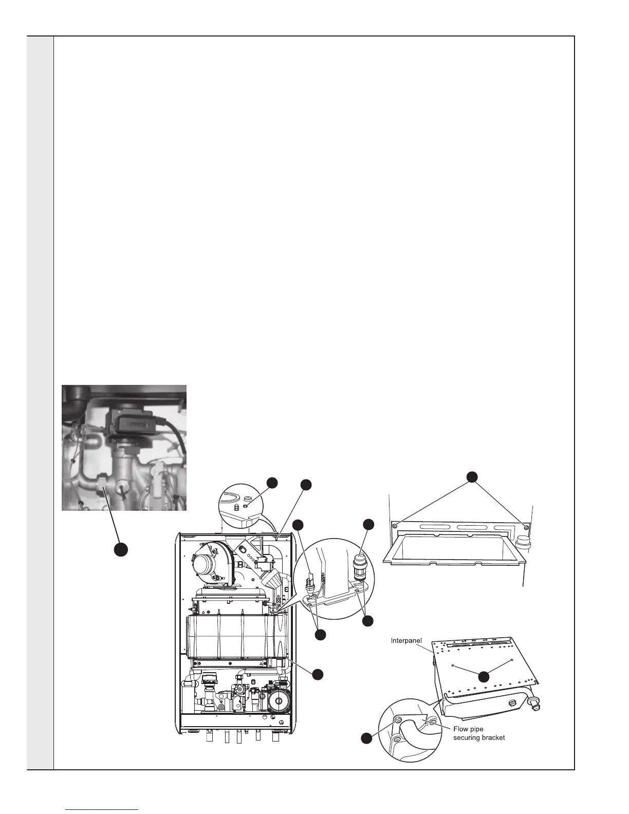
HEAT ENGINE REPLACEMENT
14. Remove the automatic air vent. Refer to Frame 71.
15. Undo the M5 x 12 screws securing the bottom flue
manifold casting and remove.
16. Remove the M5 screw and remove the return pipe
securing bracket by sliding forwards.
17. Remove the overheat thermostat and the control
thermistor. Refer to Frame 57.
18. Unscrew the brass union connection to release the flow
pipe.
19. Remove the condensate trap/ siphon. Refer to Frame 64.
20. Loosen the 2 bottom M5 screws securing the inter panel to
the back panel and remove the 2 upper M5 screws.
21. Slide the heat exchanger and inter panel assembly
upward to disengage and remove from the casing,
complete with the flow pipe.
22. Remove the 2 M6 countersunk screws, remove the inter
panel and transfer to the new heat exchanger.
23. Remove the M5 screw and remove the flow pipe securing
bracket.
24. Remove the flow pipe and transfer to the new heat
exchanger.
25. Reassemble in reverse order, replacing gaskets or seals
if any sign of damage or deterioration is evident.
Note. The heat exchanger is supplied with new combustion
chamber insulation boards. These should be fitted (refer
to Frame 63 before the burner and fan / venturi
assembly and before the ignition and detection
electrodes are replaced).
26. Refill the boiler. Refer to Frame 32.
27. Check operation of the boiler. Refer to Frame 52.
esp8869
20
12
10
11
14
15
15
16
23
22
18
SERVICING

 Loading...