18
INSTALLATION
Esprit - Installation and Servicing
203707A01
esp8914
1
2
169mm
Extended
centre
line
12
WALL MOUNTING TEMPLATE
11
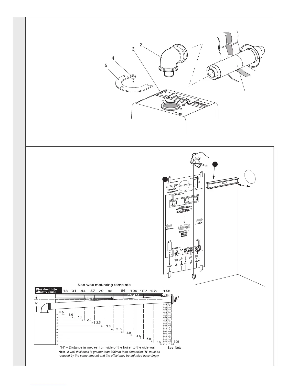
FLUE ASSEMBLY - Exploded View
An optional flue duct extension kit is required for
wall thicknesses greater than :
Side 365mm (14
3/8")
Rear 426mm (15
3/4").
Rear flue arrangement shown
nm8761
LEGEND
1. Duct assembly.
2. Flue turret.
3. Turret gasket.
4. M5 x 10 pozi screw.
5. Turret clamp.
1
esp8822
Note.
The template shows the positions of the fixing holes and the
rear flue outlet hole centre for standard installation. Care
MUST be taken to ensure the correct holes are drilled.
1. Tape template into the selected position. Ensure
squareness by hanging a plumbline as shown.
2. If fitting a side flue extend the flue centre line onto the side
wall and measure in 169mm for standard installation.
Note. If using stand-off kit distance increases to 206mm.
3. Mark onto the wall the following:
a The wall mounting plate screw
positions (choose one from each
group).
b. The position of the flue duct hole
(see diagram).
Note. Mark the centre of the hole as well
as the circumference
4. Remove the template from the wall.
INSTALLATION
 Loading...