10
GENERAL
icos system - Installation and Servicing
3
SYSTEM REQUIREMENTS
Notes
a. The method of filling, refilling, topping up or flushing
sealed primary hot water circuits from the mains via
a temporary hose connection is only allowed if
acceptable to the local water authority.
b. Antifreeze fluid, corrosion and scale inhibitor fluids
suitable for use with boilers having aluminium heat
exchangers may be used in the central heating
system.
Advice should be sought from a local water
treatment company.
Safety valve setting bar 3.0
Vessel charge pressure bar 0.5 to 0.75
System pre-charge pressure bar None 1.0
System volume Expansion vessel
(litres) volume (litres)
25 1.6 1.8
50 3.1 3.7
75 4.7 5.5
100 6.3 7.4
125 7.8 9.2
150 9.4 11.0
175 10.9 12.9
190 11.9 14.0
200 12.5 14.7
250 15.6 18.4
300 18.8 22.1
For other system volumes
multiply by the factor across 0.063 0.074
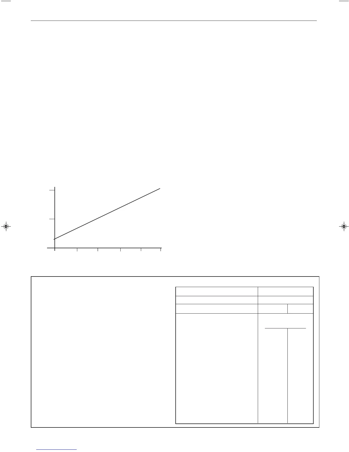
Pressure Drop Across Boiler
(metres water)
0.5
1.0
Boiler Output (kW)
8.8 11.7 14.7 17.6 20.5
23.4
Ecl 1603
WATER CIRCULATION SYSTEM
IMPORTANT.
A minimum length of 1metre of copper pipe MUST be fitted to
both flow and return connections from the boiler before
connection to any plastic piping.
The central heating system should be in accordance with
BS.6798 and, in addition, for smallbore and microbore
systems, BS.5449.
The hot water storage cylinder MUST be of the indirect type and
should preferably be made of copper.
Single feed, indirect cylinders MUST NOT be used. The
appliances are NOT suitable for gravity central heating nor are
they suitable for the provision of gravity domestic hot water.
The hot water cylinder and ancillary pipework, not forming part
of the useful heating surface, should be lagged to prevent heat
loss and any possible freezing - particularly where pipes run
through roof spaces and ventilated underfloor spaces.
WATER TREATMENT - see Frame 6
The hydraulic resistance of the boilers, at
MAXIMUM OUTPUT
,
with an 11
o
C (20
o
F) temperature differential, is shown in
Graph 1.
Graph 1 - Water flow rate and pressure loss
BOILER CONTROL INTERLOCKS
Ideal Stelrad Group recommend that heating systems utilising
full thermostatic radiator valve control of temperature in
individual rooms should also be fitted with a room thermostat
controlling the temperature in a space served by radiators not
fitted with such a valve as stated in BS. 5449.
When thermostatic radiator valves are used, the space heating
temperature control over a living area having a heating
requirement of at least 0.9kW (3000Btu/h) of the boiler heat
output should be achieved using a room thermostat whilst
other rooms are individually controlled by thermostatic radiator
valves. A higher proportion of TRVs may be used, provided that
a bypass between the boiler flow and return is fitted, to ensure
adequate flow when all TRVs are closed.
For further information refer to the 'Good Practice Guide 143', a
publication of the Energy Efficiency Office, available from the
Building Research Establishment, Garston, Watford WD2 7JR.
Tel: +44 (0) 1923 664258.
ELECTRICAL SUPPLY
WARNING. The appliance MUST be efficiently earthed.
Wiring external to the appliance MUST be in accordance with
the current I.E.E. (BS.7671) Wiring Regulations and any local
regualtions which apply. For Ireland reference should be made
to the current ETCI rules for electrical installations.
The point of connection to the mains should be readily
accessible and adjacent to the boiler.
Note. The fan voltage is 325V DC.
CONDENSATE DRAIN - Refer to Frames 22-24
A condensate drain is provided on the boiler. This drain must
be connected to a drainage point on site. All pipework and
fittings in the condensate drainage system MUST be made of
plastic - no other materials may be used.
IMPORTANT.
Any external runs must be insulated
The drain outlet on the boiler is standard 21.5mm (3/4")
overflow pipe.

 Loading...