17
INSTALLATION
icos system - Installation and Servicing
FLUE OUTLET
Notes.
1. It is recommended that a support bracket is fitted for
every 1 meter of extension pipe used and a bracket
should be used at every joint, to ensure pipes are held at
the correct angle.
If a slip joint coupling is to be used then a bracket
should be used to secure the collar.
2. When extension ‘D’ packs are used the flue duct MUST
be inclined at 1.5 degrees to the horizontal to allow
condensate to drain back into the boiler and out through
the condensate drain.
3. If the telescopic ‘B’ pack, or horizontal flue terminal (600
long) only are used, they may be mounted horizontally.
The 1.5 degreesis taken care of by the inclination of the
flue within the air pipe.
4. If the boiler is to be installed with upward piping routed
behind the boiler then the optional stand-off kit should
be used. Care must be taken when cutting the ducts and
marking the wall to suit this condition.
5. Only use water as a lubricant during assembly. Do not
use mineral based oils.
12A
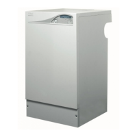
DETERMINING THE FLUE LENGTH AND FLUE PACKS REQUIRED, CONT'D
Total Flue length dimension Flue
(measuring from CL of turret to outside wall)
Rear flue Side flue Extra packs
dim. X+160 dim. L+195 required
Up to 595 mm Up to 595 mm none
Up to 1545 mm Up to 1545 mm Pack D - 1 off
Up to 2495 mm Up to 2495 mm Pack D - 2 off
Up to 3445 mm Up to 3445 mm Pack D - 3 off
Up to 4395 mm Up to 4395 mm Pack D - 4 off
Up to 5345 mm Up to 5345 mm Pack D - 5 off
Up to 6000 mm Up to 6000 mm Pack D - 6 off
1
nm8760
13
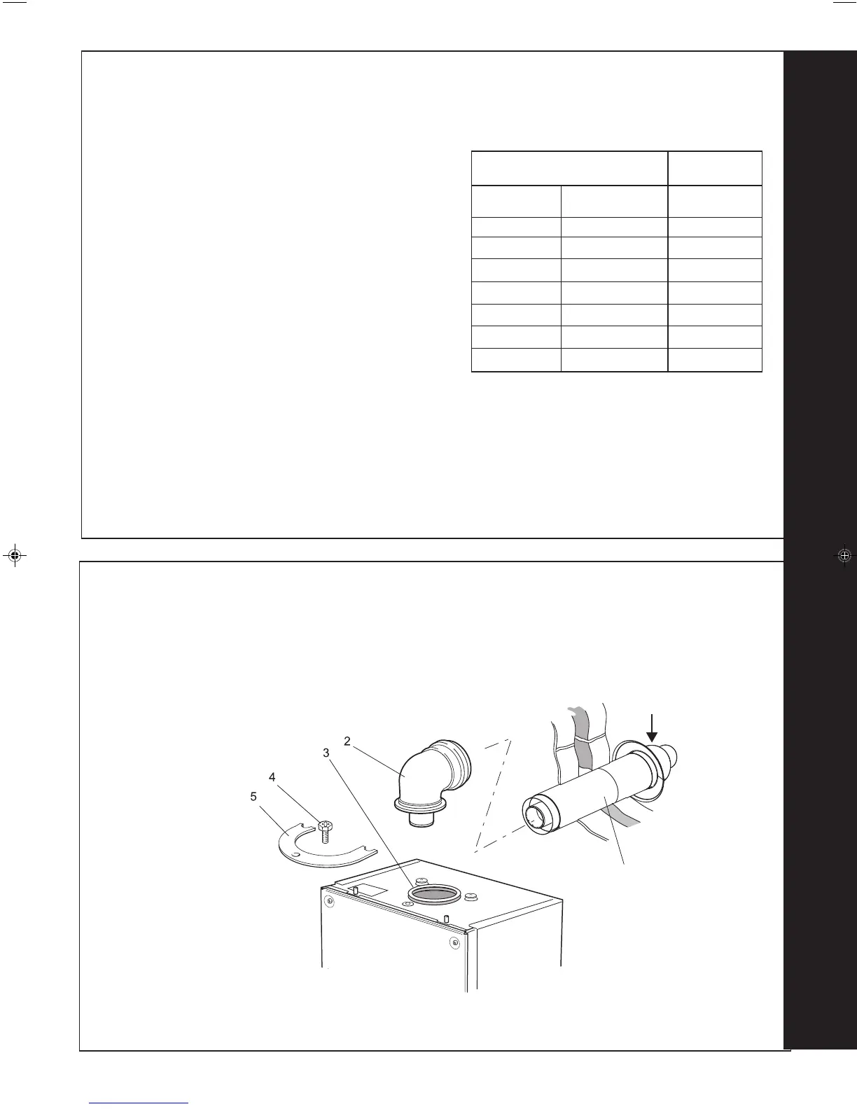
FLUE ASSEMBLY - Exploded View
An optional flue duct extension kit is
required for wall thicknesses greater
than :
Side 395mm
Rear 435mm
Rear flue arrangement shown
LEGEND
1. Duct assembly.
2. Flue Turret.
3. Turret gasket.
4. M5 x 10 pozi screw.
5. Turret clamp.
The flue terminal MUST be
fitted with the ‘TOP’
uppermost to allow the
correct fit and use of the
plume management system.
TOP
 Loading...