64
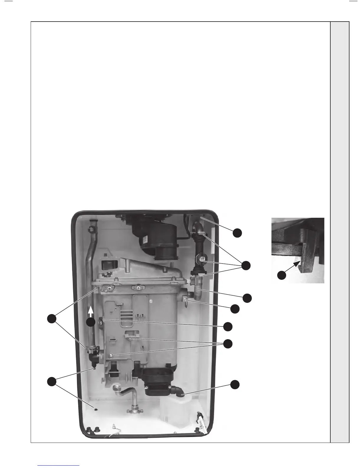
HEAT ENGINE REPLACEMENT - Refer also to Frame 10 - ‘Boiler Exploded View’
Note. To remove the ow and return pipe connections from the heat exchanger, it may be necessary to cut the pipes above the boiler.
IMPORTANT
Before starting the removal procedure, protect the gas and
electrical controls with a waterproof sheet or plastic bag.
1. Refer to Frame 51.
2. Remove rubber plug from base to drain the boiler.
3. Remove the fan / venturi assembly and place on one side.
Refer to Frame 52.
4.
Remove the burner and place on one side. Refer to Frame 54.
5. Remove the ignition and detection electrodes. Refer to
Frames 56 and 57.
6. Remove the spark generator. Refer to Frame 58.
7. Remove the gas valve. Refer to Frame 59.
8. Remove the 2 M5 screws retaining the gas valve mounting
bracket and transfer bracket to the new heat exchanger.
9. Pull the clips, retaining the water ow switch housing,
forward and remove the water ow switch.
10. Remove the screw securing the pipe to the heat exchanger
and remove the “c” clip. Lift the housing/return pipe
assembly upwards to disengage from the heat exchanger
return pipe elbow.
11. Remove the screw retaining the ow pipe bracket and
remove the bracket from its rear retention slot.
12. Pull the ow pipe to the right to disengage from the heat
exchanger.
13. Remove the condensate rubber pipe. Refer to Frame 60.
14. Remove the LH heat exchanger xing screw.
15. Pull the heat exchanger to the left to disengage the rear
retention pegs and remove the heat exchanger.
16. If replacement sump required: Rotate heat exchanger
assembly 180º. Place new sump onto heat exchanger,
ensuring correct orientation and seal is in place. Then
gently apply pressure to the base of the sump at each tab
xing point and engage tabs onto the heat exchanger.
17. Reassemble in reverse order, ensuring the heat exchanger
is correctly positioned. Replace any new ‘o’ rings supplied
with new heat exchanger and replacing gaskets or seals if
any sign of damage is evident. Note. Ensure that the ow
pipe is tted through the “V” bracket when retting.
18. Ensure the trap/siphon is lled with water. Refer to Frame
60.
19. Rell the boiler, ensuring rubber plug from base is re-tted,
and drain point is fully closed.
20. Check operation of the boiler. Refer to Frames 40 & 41.
8
14
13
11
12
9
10
2
10
17
16
Shown as 180º position
SERVICING