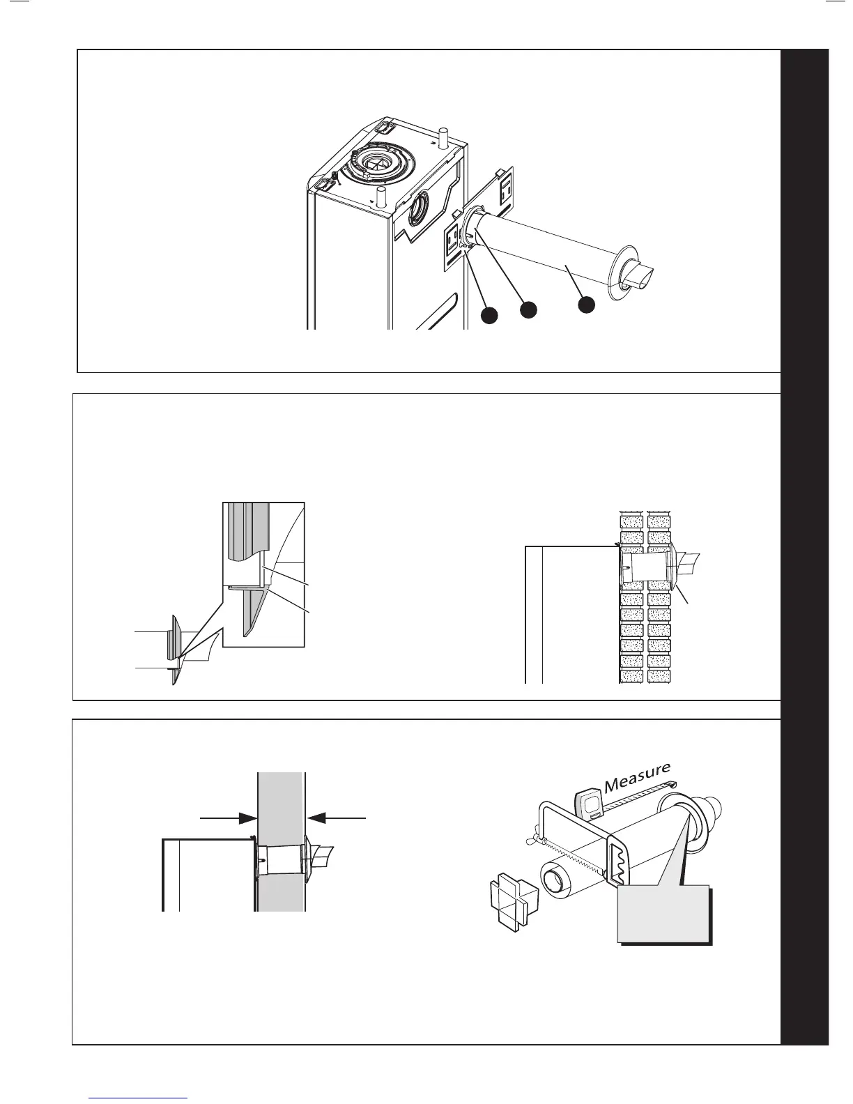
Ensure lip of wall seal is positioned
over step on plastic nose of flue terminal
(note, seal is cut away for clarity)
Step
205862-10137
Wall Seal Lip
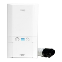
Prior to tting the ue, the rubber terminal wall seal provided
in the ue pack MUST be tted to the ue terminal as shown
below in Figure 1.
FIGURE 1
FIGURE 2
Once the ue is installed it is IMPORTANT that the rubber
terminal wall seal is pressed against the outside wall to create
an adequate seal between the ue and wall as shown in
Figure 2.
25
SETTING THE REAR FLUE LENGTH - WALL THICKNESS OF 115MM TO 442 MM
1. Measure and note wall thickness X. Refer to Frame 13.
2. Add 8mm to dimension X and, measuring from the ring, cut the outer tube
only.
3. To ensure the tube is cut square, mark the ue all the way around.
4. Cut the inner tube to a length 10mm longer to aid engagement, using the
cutting aid provided.
 Loading...