18
Installation and Servicing
Section 2 - Installation
INSTALLATION
L
B
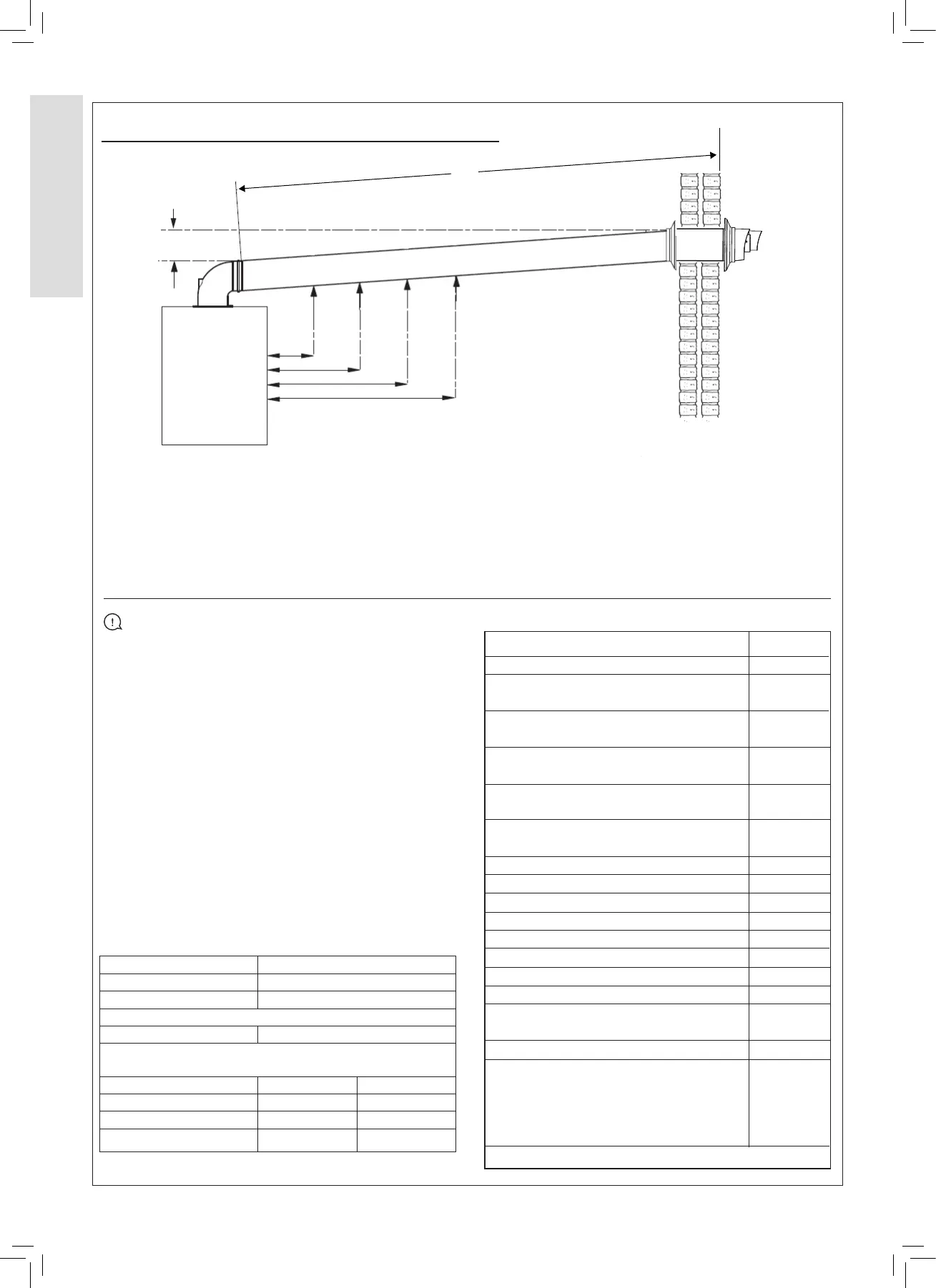
2.8 FLUES AND LOCATIONS - CONTINUED
B = Top Clearance
Top Clearance is measure from the top of the turret to the top
of the hole where the ue terminates.
L = Eective ue length.
The eective length of the ue is measured from the edge of
the turret to the ue terminal lip.
Flue systems that require extension kits must be installed
with a 1.5° decline from the ue terminal back to the boiler.
A 1.5° decline can be achieved by designing the ue with a
26 mm rise per meter length of ue.
Flue Terminal Positions
Min. Spacing*
1. Directly below, above or alongside an opening. 300 mm
2. Below guttering, drain pipes or soil pipes. 75 mm
25 mm*
3. Below eaves. 200 mm
25 mm*
4. Below balconies or a car port roof. 200 mm
25 mm*
5. From vertical drain pipes or soil pipes. 150 mm
25 mm*
6. From an internal or external corner or a 300 mm
boundary alongside the terminal. 25 mm*
7. Above adjacent ground, roof or balcony level. 300 mm
8.
From a surface or a boundary facing the terminal.
600 mm
9. From a terminal facing a terminal. 1200 mm
10. From an opening in a car port into dwelling. 1200 mm
11. Vertically from a terminal on the same wall. 1500 mm
12. Horizontally from a terminal wall. 300 mm
13. Horizontally from an adjacent window 600 mm
14. Facing an opening into an adjacent building 2000 mm
15. At an angle to the boundary 90° 300 mm
45° 600 mm
16. Parallel to a boundary 300 mm
17. Below ground level – open light well
a) Below ground <1,000 mm
b) Above oor level 300 mm
c) From side 300 mm
d) From facing surface
600 mm
*Only one reduction down to 25mm is allowed per installation.
Table 5 - Flue Terminal Position
Horizontal
Maximum Eective Flue Length
15-24 Kw 9.0 metres
30 kW 8.0 metres
Vertical
15-24/30 kW 7.5 metres
Elbows increase resistance and have an eective ue length
equivalence. The following table is an example.
Part x Resistance
45
o
elbow 2 1.2 metres
90
o
elbow 2 2.0 metres
Eective ue length 3.2 metres
IMPORTANT INFORMATION
Install the ue in accordance to BS 5440:1 2008
Position the terminal, so the products of combustion do not
cause a nuisance.
The terminal outlet duct must not be closer than 25 mm to
combustible material.
The ue is secured in the wall using either sand and cement
or heatproof silicone.
The ue must be supported by a bracket every metre of ue
length and at every change of direction. Concealed ues
must have inspection hatches no more than 1.5 metres from
joints.
Where possible inspection hatches should be located at
change of directions. Where this is not possible then bends
must be viewable from both sides.
Inspection hatches must be at least 300 mm
2
.