20
Installation and Servicing
Section 2 - Installation
INSTALLATION
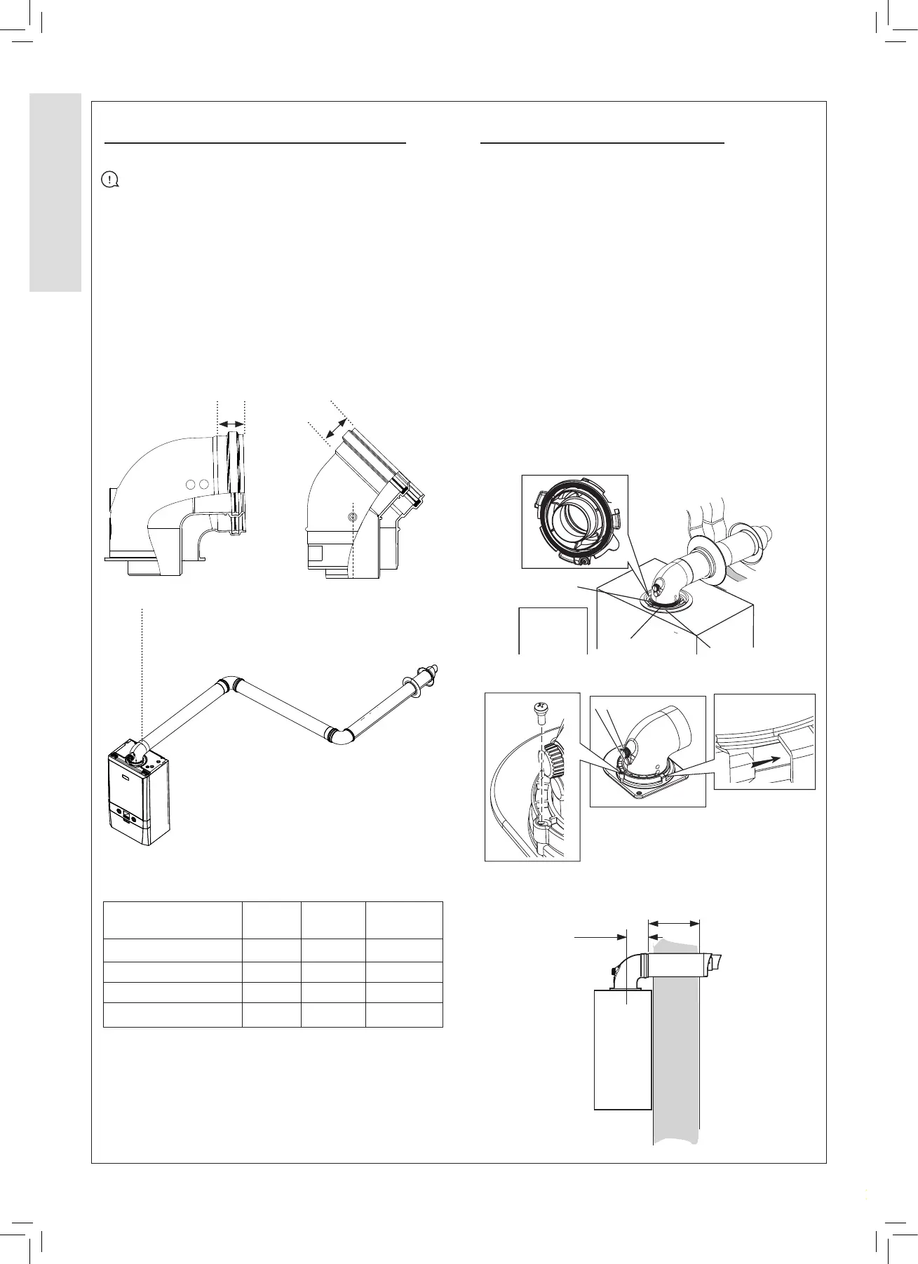
2.11 FLUE SYSTEM DIMENSIONS 2.12 FITTING THE TURRET
Flue Design
IMPORTANT:
1. Flue lengths may vary, always measure ue lengths
before cutting.
2. Eective ue length and actual ue length are dierent
measurements.
3. Eective ue length is made up of the ue length
equivalence and the ue sections between the turret,
elbows and terminal.
4. Actual ue length is the amount of ue needed to achieve
the eective ue length, this includes insertions.
Part Actual
Length
Insertion Eective
Length
1 m ue length 1 m 30 mm 970 mm
1 m ue length 1 m 30 mm 970 mm
0.6 m ue terminal 0.6 m 30 mm 570 mm
Total 2.6 m 90 mm 2510 mm
Retaining
screw
Clamp Lugs
Sample points
Flue Outlet
C
A
A - Duct Assembly
B - Flue Turret
C - Turret Clamp
D - Seal
Flue Outlet
D
B
1. Ensure the condensate trap in lled with water
2. Ensure the rubber seal is not damaged and tted
correctly on the appliance manifold.
3. Firmly hold the ue and push the turret on until it has
travelled 30 mm ensuring the ue has not rotated or
moved forward.
4. Push the turret into the manifold ensuring the upper
plastic lip is ush with the top of the manifold.
5. Fully engage the clamp location section into the manifold
location hole and rotate down onto the ange.
6. Use the securing screws to secure the clamp to the
appliance.
7. Ensure all sample points are accessible and all sample
plugs and caps are tted.
30
30
Elbow insertion (mm)Turret insertion (mm)
100mm
Edge of turret
to outside face of wall plus
44mm = ue length
A
WALL