INSTALLATION
14 Viceroy GT Range - Installation
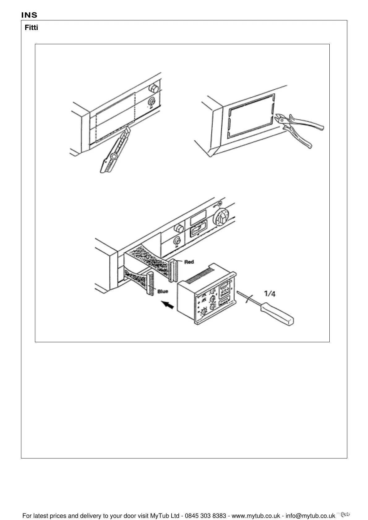
The SV-matic weather compensator is fitted in the front part
of the control panel. To do this:
1-2. Remove the blank by cutting the surface with a
stanley knife following the black line and by breaking
the perforations in the steel plate behind with a pair of snips.
3. Connect the two connections, situated behind the
blank, to the back of the SVR unit: blue connector to
the blue plug, red connector to the red plug.
4. Locate the unit by its front and fix it using the two
screws sited in the front part of the equipment
(1/4 turn clockwise)
Caution: When a two stage SV-matic weather compensator type
322 DB is fitted, the resistor and the bridge respectively fitted
between terminals 34 and 37, and 34 and 35 must be removed.
1 2
3
Fitting an SV-matic weather compensator
8219-EN-9
8219-EN-14
8219-EN-11
 Loading...


