INSTALLATION
Viceroy GT Range - Installation 15
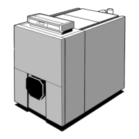
STANDARD CONTROL PANEL
The connections are made on the terminal strip in the control
panel, accessible by opening the panel
(3 screws at the back - see diagram).
The connection cables are directed towards the front via the
two cut outs in the rear panel of the boiler, and routed in the
cable run to the control panel via the 2 rectangular cut outs
in the front top panel.
The burner control circuit generally a 2-stage burner, is fitted
with 2 European 7 and 4 pin plugs supplied with the boiler,
which simply need to be fitted into the female plugs supplied
with the burners. In the case of a burner not fitted with
female plugs, remove the plugs on the burner cable from the
boiler and connect the leads to the terminal bar on the
burner.
Burner connection
REAR FRONT
8259N2
 Loading...


