38 Viceroy GT Range - Installation
ASSEMBLY
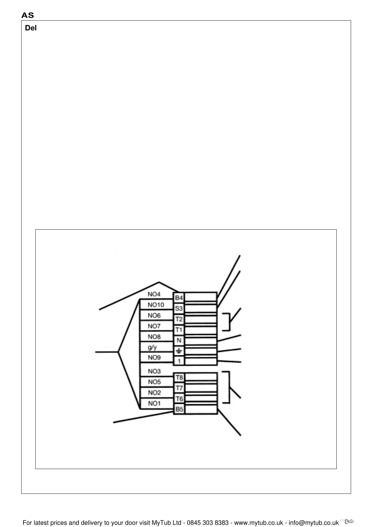
Deluxe Control Panel Burner Connection
1st Stage operating indicator
Burner malfunction indicator
TCH1
Neutral
Earth
TS
TCH2
2nd Stage operating indicator
Additional plug for
2-stage burner
Plug for single
stage burner
The Burner Control circuit is fitted with 2 standard European
connector-plugs and can be directly to the burners, fitted
with connector-sockets. In the case of a burner not fitted
with sockets, remove the plugs on the burner cable from the
boiler and connect the leads to the terminal bar on the
burner, proceeding as follows:
No.(9) [1] Control circuit phase interrupted in panel by
safety Thermostat TS, Limit Thermostat TS and
panel ON/OFF switch ZG. Connect to control
circuit live terminal burner.
NOTE: The connection terminal for this control
phase must be separate from those of the power
supply phase(s) which are wired direct to the
burner via the installer supplied burner mains relay.
No.(8) [N] Neutral from control panel interrupted by panel
ON/OFF switch. Connect to Neutral terminal of
burner control box.
No.(7) T1 Live feed from burner control circuit downstream
of burner ON/OFF switch. Connect to live side of
first stage control thermostat (High temperature
setting).
No.(6) T2 Return from 1st stage control thermostat (High
temperature setting). Live on this lead, hence on
T2 allows burner to fire on low fire in a 2 stage burner.
No.(10) S3 Burner lock indicator. Feeds signal from lockout
terminal on burner control box to lock out
indicator on boiler control panel.
No.(4) B4 Feed to 1st stage operating indicator from low fire
control. Indicates low fire in operation. essentially
feed back from live on No.(6) T2.
No.(2) T6 Live feed from burner control circuit downstream
of burner ON/OFF switch. Connects to live side of
2nd stage control thermostat (Low setting
thermostat).
No.(3) T8 Return from 2nd stage control thermostat (Low
temperature setting). Live on this lead, hence on
T8 allows burner to fire on high fire in a 2 stage
burner.
No.(5) T7 Back contact from 2nd stage control thermostat
(Low temperature setting). Live on this lead,
hence T7 indicates high fire out of operation (used
for modulating burners only)
No.(1) B5 Feed to 2nd stage operating indicator from burner
high fire control to boiler panel. Indicates high fire
in operation. Essentially feed back from live on
No.(3) T8.
g/y Earth
 Loading...


