Engineering
HR9Z-B2192 8/2020 41
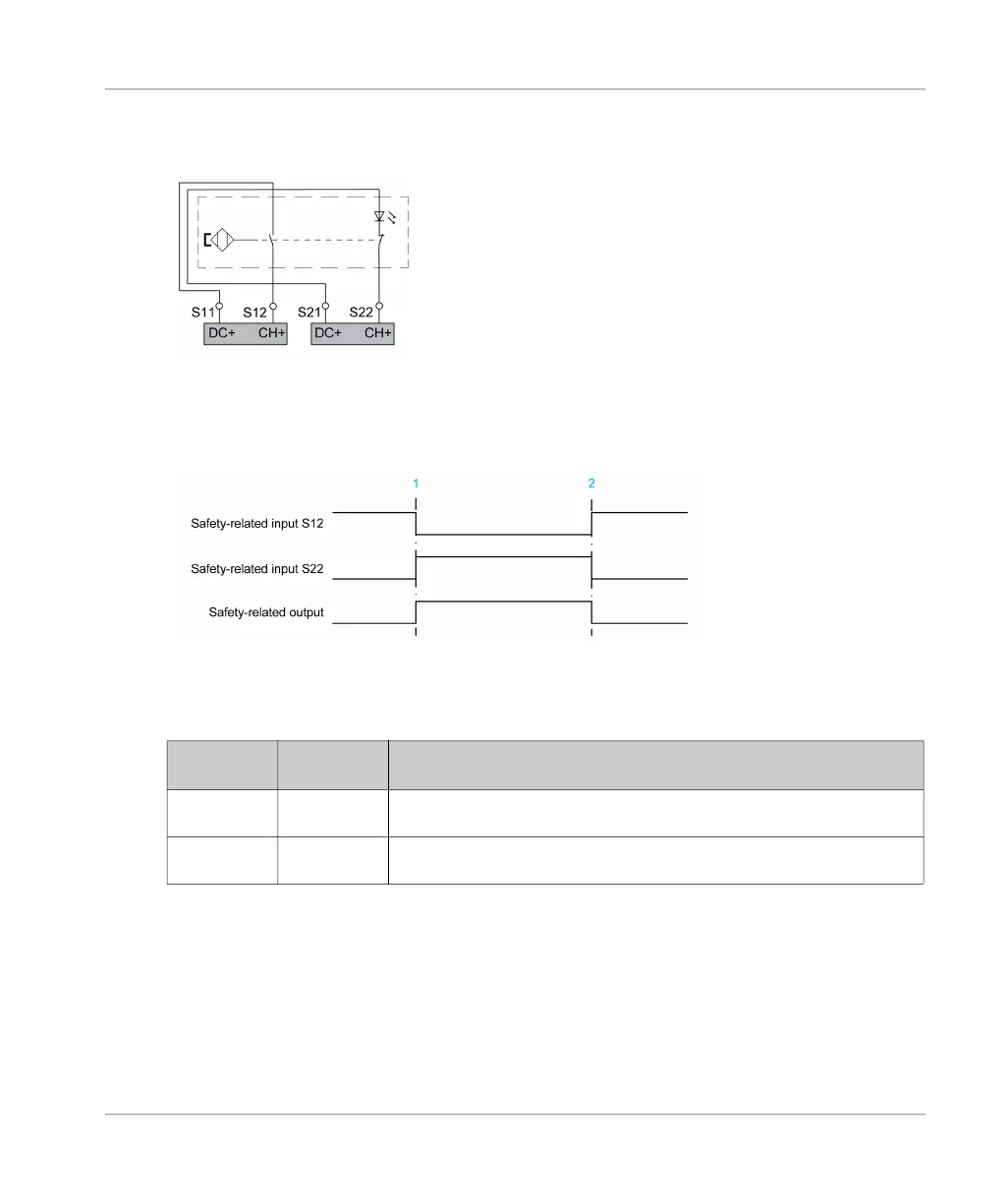
Two safety-related inputs with one input channel each with antivalent behavior (magnetic switch
with NO at S12 and NC at S22):
If the level at terminal S12 is logically 0 and the level at terminal S22 is logically 1, the safety-related
input is activated.
Timing diagram for two safety-related inputs with one input channel each with antivalent behavior:
1 = Activation, transition to operating state Run: Outputs Energized
2 = Deactivation, transition to operating state Run: Outputs Deenergized (defined safe state)
Truth table for two safety-related inputs with one input channel each with antivalent behavior:
Identical signal states are only permissible within the synchronization time
(see page 42)
.
Otherwise, identical signal states trigger an alert.
The truth table applies to the wiring diagrams presented for the application functions.
If the magnetic switch in the wiring example above is used for guard monitoring, this means that
the magnetic switch is presented in the activated state and the guard is closed.
Consult the manual of the sensor/device you want to use for your application function for details
on signal state required for activation and deactivation as defined in the present document.
Signal State
at S12
Signal State
at S22
Activation State and Operating State
(see page 35)
0 1 Safety-related input channel activated, operating state Run: Outputs
Energized
1 0 Safety-related input channel deactivated, operating state Run: Outputs
Deenergized