4: B
ASIC
I
NSTRUCTIONS
4-12 FC6A S
ERIES
MICROS
MART
L
ADDER
P
ROGRAMMING
M
ANUAL
FC9Y-B1726
CNT, CDP, and CUD (Counter)
Three types of counters are available; adding (up) counter CNT, dual-pulse reversible counter CDP, and up/down selection
reversible counter CUD. A total of 512 counters can be programmed in a user program. Each counter must be allocated to a unique
number C0 through C511.
For details about device ranges, see "Device Addresses" on page 2-1.
To indirectly specify the value, specify it with a data register number, and specify the value of the data register in the range of 0 to 65,535.
CNT (Adding Counter)
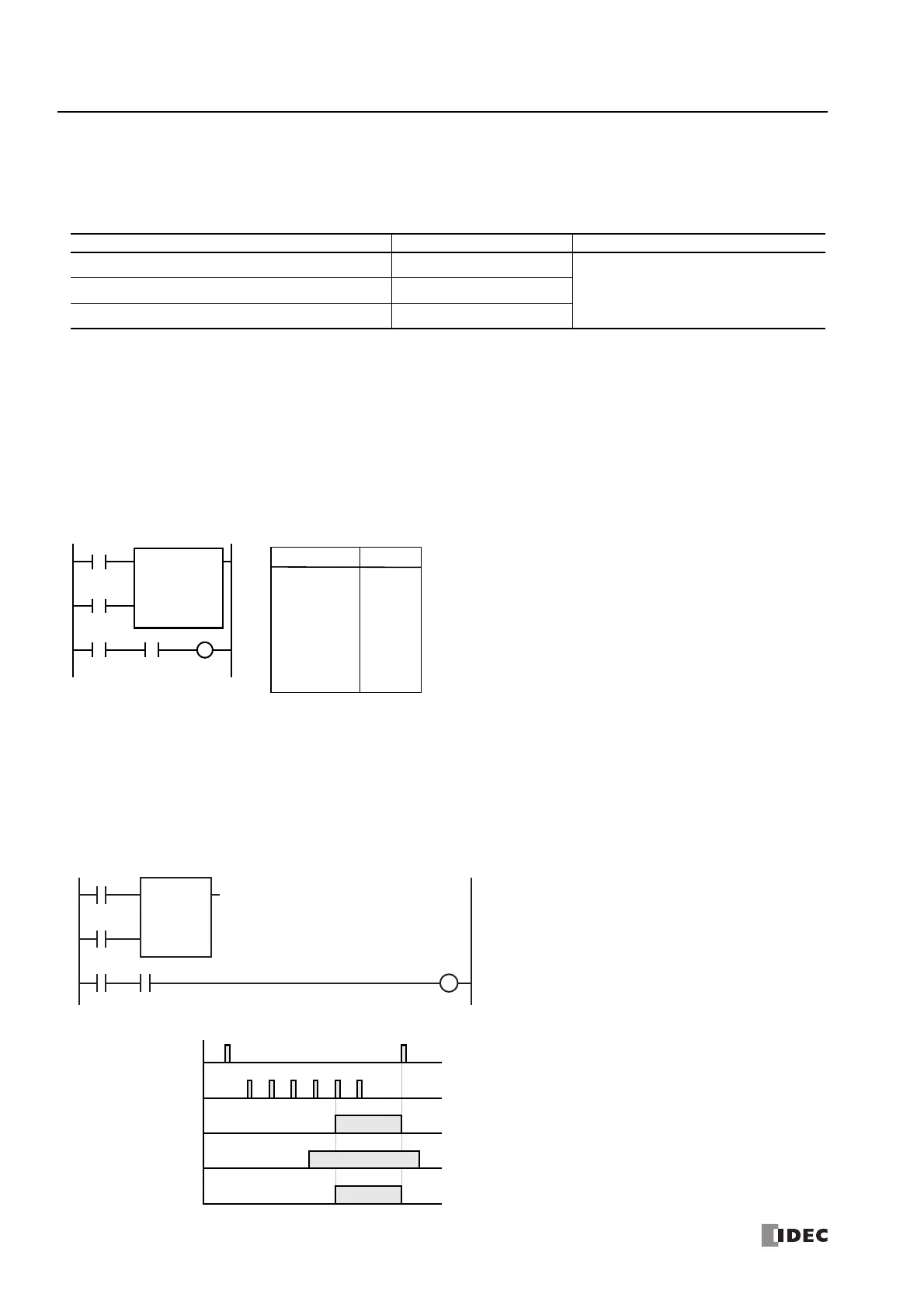
When counter instructions are programmed, two addresses are required. The circuit for an adding (UP) counter must be
programmed in the following order: reset input, pulse input, the CNT instruction, and a counter number C0 through C511, followed
by a counter preset value from 0 to 65,535.
The preset value can be designated using a decimal constant or a data register. When a data register is used, the data of the data
register becomes the preset value.
• The CNT instruction cannot be used in an interrupt program.
• When the reset input is on, all pulse inputs are ignored.
• While the reset input is off, the counter counts the leading edges of pulse inputs and compares them with the preset value.
• When the reset input changes from off to on, the current value is reset.
• When the current value reaches the preset value, the counter turns output on. The output stays on until the reset input is turned on.
Note: Certain instructions can be programmed in a series after a counter instruction in WindLDR. These instructions are not automatically
connected to the right power rail as shown in the above ladder diagram. (Refer to the below diagram.)
For details, see "Counter Circuit" on page 4-15.
Counter Device Address Preset Value
CNT (adding counter) C0 to C511 Constant: 0 to 65,535
CDP (dual-pulse reversible counter) C0 to C511
Data registers: D0 to D7999
D10000 to D61999
CUD (up/down selection reversible counter) C0 to C511
Ladder Diagram
I2 C0
CNT C0
5
I1
Reset
Pulse
I0
Q0
LOD
LOD
CNT
LOD
AND
OUT
I0
I1
C0
5
I2
C0
Q0
Instruction Data
Program List
I0000
I0001
I0002
C000 Q0000
R
P
CNT C000
5
Reset Input I0
ON
OFF
Pulse Input I1
ON
OFF
Counter C0
ON
OFF
Timing Chart
Output Q0
ON
OFF
1
Input I2
• • •
23456
ON
OFF
 Loading...
