FC6A S
ERIES
MICROS
MART
L
ADDER
P
ROGRAMMING
M
ANUAL
FC9Y-B1726 5-5
5: M
OVE
I
NSTRUCTIONS
MOVN (Move Not)
Valid Devices
For valid device address ranges, see "Device Addresses" on page 2-1.
Special internal relays cannot be designated as D1.
When T (timer) or C (counter) is used as S1, the timer/counter current value (TC or CC) is displayed. When T (timer) or C (counter) is used as D1,
the data is written in as a preset value (TP or CP) which can be 0 through 65,535.
Valid Data Types
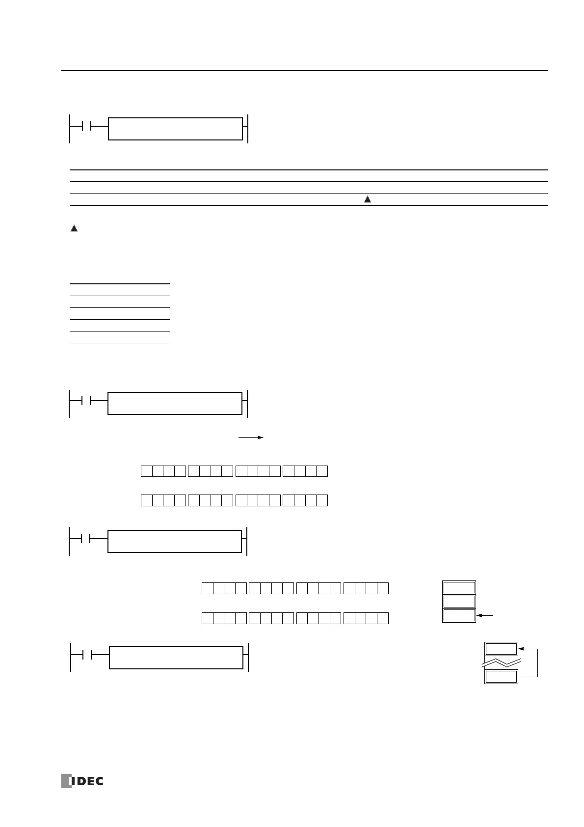
Examples: MOVN
S1 NOT → D1
When input is on, 16- or 32-bit data from device assigned by S1 is inverted bit by bit
and moved to device assigned by D1.
REP
**
S1(R)
*****
D1(R)
*****
MOVN(*)
Device Function I Q M R T C D P Constant Repeat
S1 (Source 1) First device address to move XXXXXXX— X 1-99
D1 (Destination 1) First device address to move to — X X X X X — — 1-99
W (word) X When a bit device such as I (input), Q (output), M (internal relay), or R (shift register) is assigned as the source
or destination, 16 points (word or integer data) or 32 points (double-word or long data) are used. When repeat is
set for a bit device, the quantity of device bits increases in 16- or 32-point increments.
When a word device such as T (timer), C (counter), or D (data register) is assigned as the source or destination, 1
point (word or integer data) or 2 points (double-word or long data) are used. When repeat is set for a word device, the
quantity of device words increases in 1- or 2-point increments.
I (integer) X
D (double word) X
L (long) X
F (float) —
M10 NOT → M50
When input I0 is on, the 16 internal relays, starting with M10 assigned by source device
S1, are inverted bit by bit and moved to 16 internal relays starting with M50 assigned by
destination device D1.
The ON/OFF statuses of the 16 internal relays M10 through M17
and M20 through M27 are inverted and moved to 16 internal
relays M50 through M57 and M60 through M67. M50 is the LSB
(least significant bit), and M67 is the MSB (most significant bit).
I0
REPS1 –
M10
D1 –
M50
MOVN(W)
M10 through M17, M20 through M27 NOT M50 through M57, M60 through M67
Before inversion
0 1 0010 0 0 0 1 0010 1 1
MSB LSB
S1
After inversion
1 0 1101 1 1 1 0 1101 0 0
MSB LSB
D1
(M0027-M0010):
(M0067-M0050):
810 NOT → D2
When input I1 is on, decimal constant 810 assigned by source device S1 is converted into
16-bit binary data, and the ON/OFF statuses of the 16 bits are inverted and moved to
data register D2 assigned by destination device D1.
I1
REPS1 –
810
D1 –
D2
MOVN(W)
D1
D0
64725
D2
810
Before inversion (810):
0 0 1000 0 1 0 1 1000 1 0
MSB LSB
S1
After inversion (64725):
1 1 0111 1 0 1 0 0111 0 1
MSB LSB
D1
D30 NOT → D20
When input I2 is on, the data in data register D30,
assigned by S1, is inverted bit by bit and moved to data
register D20 assigned by D1.
I2
REPS1 –
D30
D1 –
D20
MOVN(W)
 Loading...
