FC6A S
ERIES
MICROS
MART
L
ADDER
P
ROGRAMMING
M
ANUAL
FC9Y-B1726 19-45
19: PID C
ONTROL
I
NSTRUCTION
Application Example
This section describes an application example using the PIDA instruction.
Note: You must change the settings according to the application's actual system configuration and operating status.
The following two system configurations are described for applications that set the set point for the control target temperature to
200°C and perform PID control.
• PID control via ON/OFF output
• PID control via analog output
Operation
• PID control is performed based on the temperature input to the analog I/O cartridge and the manipulated variable is output.
The set point is 200ºC.
• The control mode is PID (PID control) and the control action is reverse control action.
• Alarm 1 output (S3+3) is turned ON when the process variable reaches 250°C, and the heater is stopped or the power is adjusted.
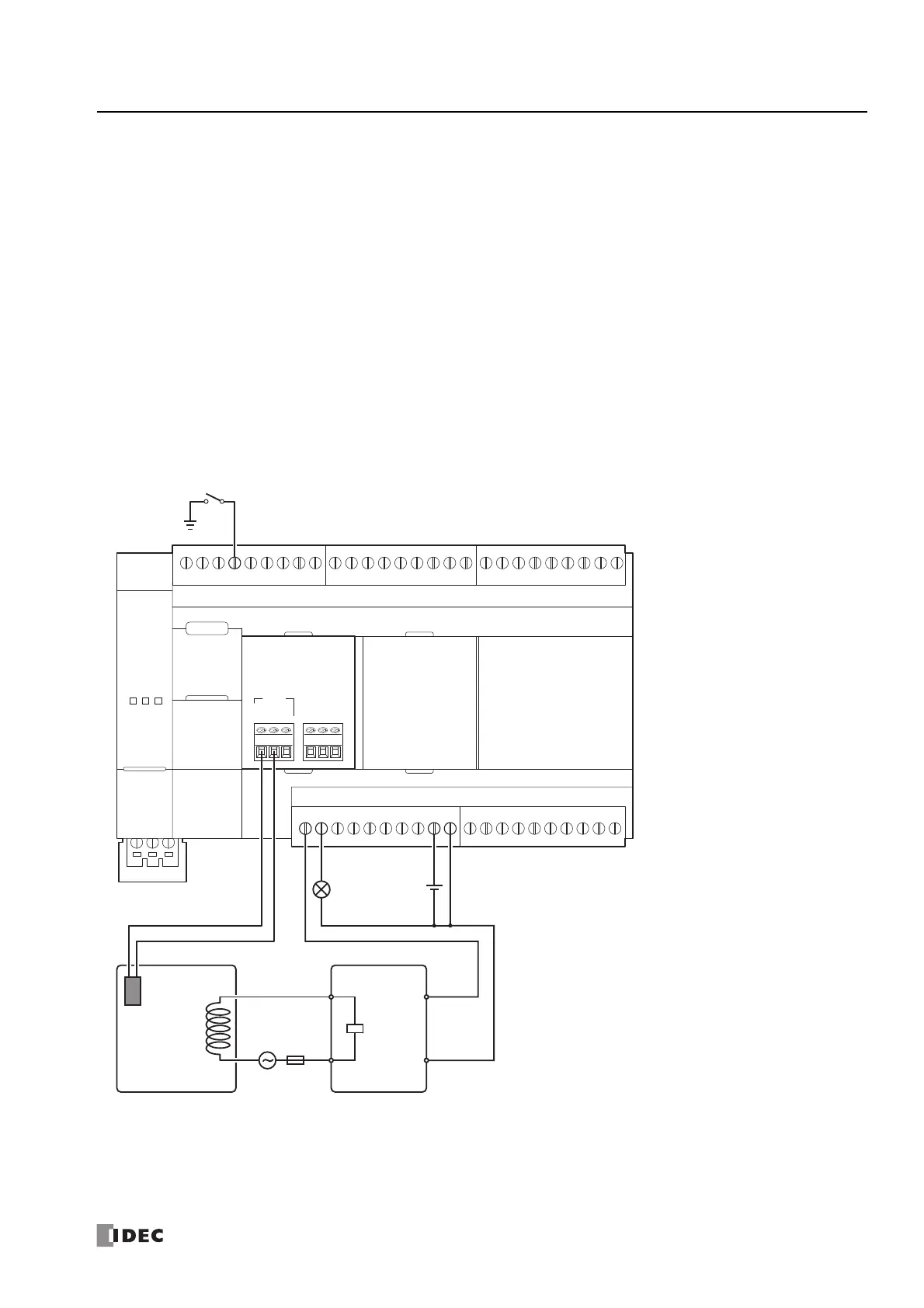
PID control via ON/OFF output
System configuration
IN0
RTD
TC
A
+
B
-
B’
NC
FC6A-PJ2CP
SSR
(Solid State Relay)
+
–
Q1Q0 COM0(
+
)V0(
-
)
I0
Fuse
Alarm Lamp
Thermocouple
Heater
+–
 Loading...
