9: S
HIFT
/ R
OTATE
I
NSTRUCTIONS
9-4 FC6A S
ERIES
MICROS
MART
L
ADDER
P
ROGRAMMING
M
ANUAL
FC9Y-B1726
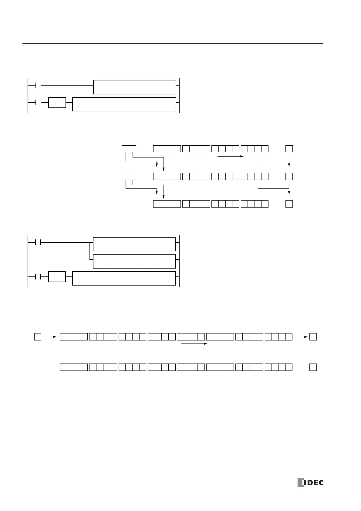
Example: SFTR
•Data Type: Word
•Data Type: Double Word
M8120 is the initialize pulse special internal relay.
When the CPU starts operation, the MOV (move) instruction sets
29 to data register D10.
Each time input I0 is turned on, 16-bit data of data register D10
is shifted to the right by 2 bits as assigned by device Bits. The last
bit status shifted out is set to special internal relay M8003 (carry
or borrow). Zeros are set to the MSB.
M8120
REP
SOTU
I0
S1 –
29
D1 –
D10
S1
D10
Bits
2
SFTR
MOV(W)
S2
0
N_B
16
0Before shift: D10 = 29 0 0 0000 0 0 0 0 0110 1 1
CY
M8003
MSB LSB
D10
0After first shift: D10 = 7 10 0000 0 0 0 0 1000 0 1
CY
M8003
MSB LSB
D10
Bits to shift = 2
0
10 0000 0 0 0 0 0000 0 0After second shift: D10 = 1
CY
M8003
MSB LSB
D10
1
0
0
Shift to the right
M8120 is the initialize pulse special internal relay.
When the CPU starts operation, the MOV (move) instructions set
65,535 and 0 to data registers D10 and D11, respectively.
Each time input I0 is turned on, 32-bit data of data registers D10
and D11 is shifted to the right by 1 bit as assigned by device Bit.
D10 is the low word, and D11 is the high word.
The last bit status shifted out is set to special internal relay
M8003 (carry or borrow). Ones are set to the MSB.
M8120
REP
SOTU
I0
S1 –
65535
D1 –
D10
S1
D10
Bits
1
SFTR
MOV(W)
S2
1
N_B
32
REPS1 –
0
D1 –
D11
MOV(W)
Bits to shift = 1
1
Before shift:
1 1 1111 1 1 1 1 1111 1 1
CY
M8003
MSB LSB
D10
1
After shift:
11 1110 1 1 1 1 1111 1 1
CY
M8003
MSB LSB
D10·D11
Shift to the right
00 0001 0 0 0 0 0000 0 0
0 0 0000 0 0 0 0 0000 0 0
D11
D11 D10
S2
 Loading...
