9: S
HIFT
/ R
OTATE
I
NSTRUCTIONS
9-6 FC6A S
ERIES
MICROS
MART
L
ADDER
P
ROGRAMMING
M
ANUAL
FC9Y-B1726
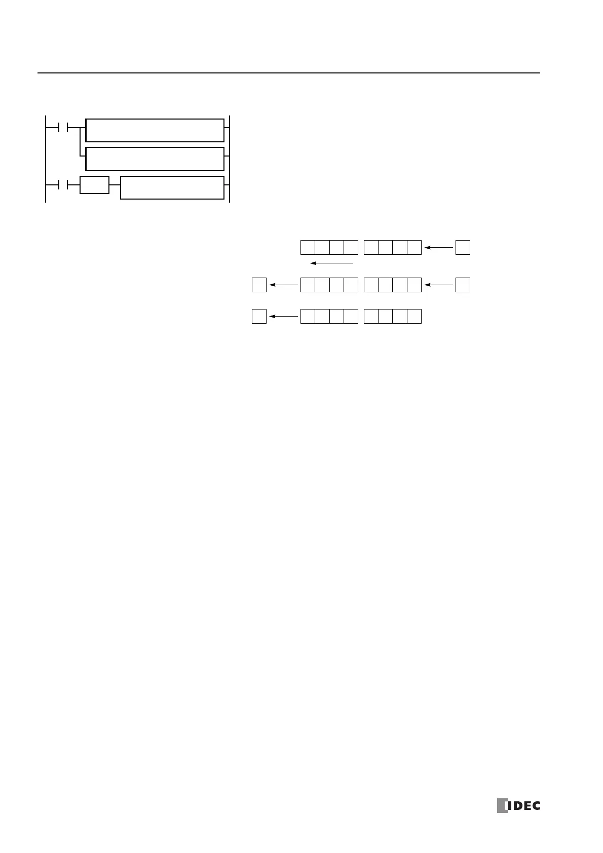
Example: BCDLS
M8120 is the initialize pulse special internal relay.
When the CPU starts operation, the MOV (move) instructions set 123 and 4,567 to
data registers D10 and D11, respectively.
Each time input I0 is turned on, the 32-bit binary data of data registers D10 and D11
assigned by S1 is converted into 8 BCD digits, shifted to the left by 1 digit as assigned
by device S2, and converted back to 32-bit binary data.
Zero is set to the lowest digit after each shift.
REP
SOTU
I0
S1 –
4567
D1 –
D11
S1
D10
S2
1
BCDLS
MOV(W)
M8120
REPS1 –
123
D1 –
D10
MOV(W)
Before shift:
After first shift:
0 2 31
D10 D11
Shift to the left
4 6 75 0
1 3 42 5 7 0
6
0
After second shift:
MSD LSD
2 4 53 6 0 071
0
When S2 = 1 (digits to shift)
 Loading...
