18: P
ULSE
O
UTPUT
I
NSTRUCTIONS
18-30 FC6A S
ERIES
MICROS
MART
L
ADDER
P
ROGRAMMING
M
ANUAL
FC9Y-B1726
(4) D1 (destination 1): Operation status
D1 specifies the first internal relay of the internal relays to use with the RAMPL instruction. Starting from the specified
internal relay, 4 sequential internal relays are used. Specify the first internal relay so that the device range is not exceeded.
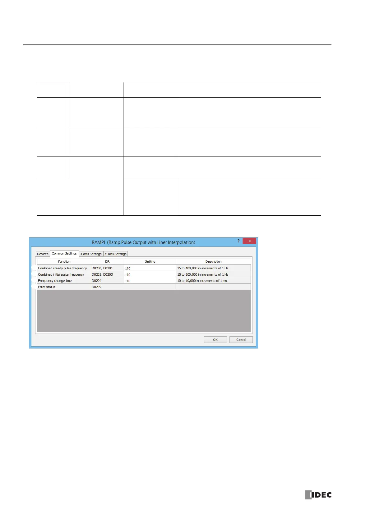
■ Common Settings tab
(5) Combined steady pulse frequency
This setting specifies the steady pulse frequency after the pulse frequency is increased. The output frequency error is within
±5%.
The steady pulse frequency for the X and Y axes that is calculated from the combined steady pulse frequency will be lower
than the combined steady pulse frequency. Set this so that the steady pulse frequency of the X and Y axes does not fall
below 15 Hz.
(6) Combined initial pulse frequency
Specifies the frequency when pulse output starts. The output frequency error is within ±5%.
The initial pulse frequency for the X and Y axes that is calculated from the combined initial pulse frequency will be lower
than the combined initial pulse frequency. Set this so that the initial pulse frequency of the X and Y axes does not fall below
15 Hz.
(7) Frequency change time
Specify the time for increasing and decreasing the pulse frequency. Set the value in the range of 10 to 10,000 ms in
increments of 1 ms. The first digit of the setting is handled as zero. For example, if 144 is entered, the set value is handled
as 140 ms.
Storage
Destination
Function Setting
Starting
number+0
Pulse output ON
0: Pulse output OFF
1: Pulse output ON
This relay turns on during pulse output.
This relay turns off when pulse output stops.
This relay turns off when the specified number of pulses are output
and output ends.
Starting
number+1
Pulse output complete
0: Pulse output not
complete
1: Pulse output
complete
This relay turns on when pulse output is complete.
This relay turns off when pulse output starts.
Starting
number+2
Pulse output status
0: Steady pulse output
1: Changing output
pulse frequency
This relay turns off when the pulse output status is steady.
This relay turns on when the pulse output is changing.
Starting
number+3
Overflow
0: None
1: Overflow has
occurred
This relay turns on when the pulses that were output have
exceeded the preset value when enable pulse counting is set.
Pulse output will continue even if an overflow occurs while changing
the frequency or during steady operation. However, counting of the
current value will stop when the overflow occurs.
 Loading...
