FC6A S
ERIES
MICROS
MART
L
ADDER
P
ROGRAMMING
M
ANUAL
FC9Y-B1726 18-51
18: P
ULSE
O
UTPUT
I
NSTRUCTIONS
Error status
Outputs the error code that corresponds to the content of an error when there is an error in the settings. If a configuration
error occurs when a step starts executing, a user program execution error will occur, and the error code 20 is stored in
D8006.
6. D2 (destination 2): Operation Status
D2 specifies the starting number of the internal relays to use with ARAMP1, ARAMP2, ARAMP3 and ARAMP4 instructions.
Starting from the specified internal relay, 5 sequential internal relays are used.
Specify the starting number so that the device range is not exceeded.
7. Preview
Displays a preview of the configured ARAMP instruction operation. The change in pulse output frequency, forward/reverse
operation, and the execution order of the steps can be checked.
The vertical axis indicates the pulse frequency and the horizontal axis indicates time.
The width of each step is locked, so the actual proportion of the horizontal axis is not accurate.
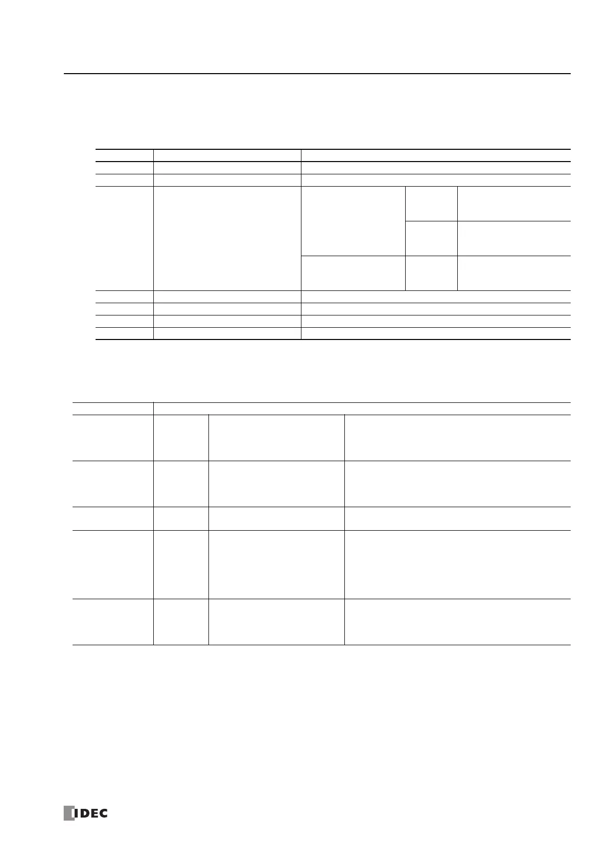
Error Code Status Description
0Normal —
3 Preset value designation error The preset value was not set between 1 to 100,000,000.
4 Steady pulse frequency designation error
All-in-One CPU module
ARAMP1,
ARAMP2
The steady pulse frequency
was not set between 15 and
100,000.
ARAMP3,
ARAMP4
The steady pulse frequency
was not set between 15 and
5,000.
CAN J1939 All-in-One CPU
module/Plus CPU module
ARAMP1 to
ARAMP4
The steady pulse frequency
was not set between 15 and
100,000.
5 Frequency change time designation error The frequency change time was not set between 10 and 10,000.
7 Step options designation error The step options were not set to a valid value.
8
Next step number destination error
The next step number was not set between 0 and 18.
9 Interrupt number destination error The interrupt number was not set between 1 and 18.
Address Description
Starting number+0
Pulse output
ON
0: Pulse output OFF
1: Pulse output ON
This relay turns on during pulse output.
This relay turns off when the ARAMP instruction output stops.
This relay turns off when the specified number of pulses are
output and output ends
Starting number+1
Pulse output
complete
0: Pulse output not complete
1: Pulse output complete
This relay turns on when pulse output completes.
This relay turns on when the step number currently being
executed is 0.
This relay turns off when the ARAMP instruction output starts.
Starting number+2
Pulse output
status
0: Steady pulse output
1: Changing output pulse frequency
This relay turns off when the pulse output status is steady.
This relay turns on when the pulse output is changing.
Starting number+3 Overflow
0: None
1: An overflow has occurred
This relay turns on when the pulses output exceed the
configured preset value.
Pulse output continues even if an the overflow occurs during
steady output or while the pulse frequency is changing.
However, pulse counting (current value data register) is
suspended at the point when the overflow occurred.
Starting number+4
Pulse output
direction
0: Forward
1: Reverse
This relay turns off when the output direction of the pulses
being output is forward.
This relay turns on when the output direction of the pulses
being output is reverse.
 Loading...
