18: P
ULSE
O
UTPUT
I
NSTRUCTIONS
18-90 FC6A S
ERIES
MICROS
MART
L
ADDER
P
ROGRAMMING
M
ANUAL
FC9Y-B1726
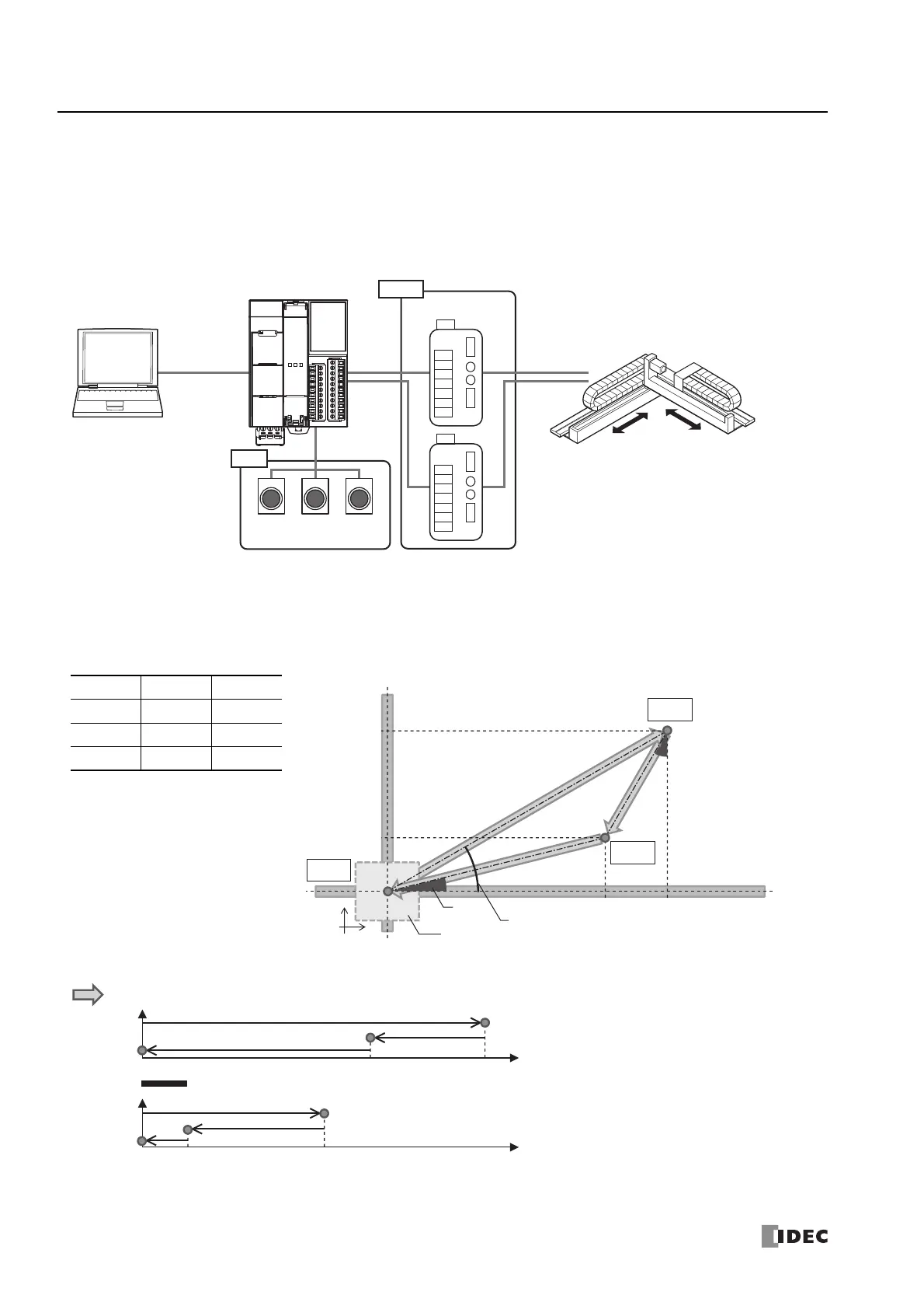
Example of Simultaneous Dual Axis Control Using the RAMPL Instruction
■ Application
Dual axis electric slider
■ System configuration diagram
Electric slider specification is treated as 0.01 mm per pulse in this example.
To learn the actual travel distance of the electric slider that will be used, check the electric slider specifications (travel distance per pulse).
■ Operation
When the stop movement switch is pressed for 3 seconds, ABS instruction will be executed to establish the origin.
When the start movement button is pressed, the electric slider moves as follows: Point A → Point B → Point C → Point A. The
electric slider stops when it reaches Point A the second time.
When the stop movement button is pressed, the moving electric slider stops.
When the zero return button is pressed, the electric slider returns to the origin (Point A) from the stopped position.
Distances in parentheses have been calculated at 0.01 mm per pulse.
Position X (cm) Y (cm)
Distances in parentheses have been calculated at 0.01 mm per pulse.
Point A 0 0
Point B 30 16
Point C 20 4
Input
Output
WindLDR
FC6A Series MICROSmart
Motor driver Dual axis electric slider
Example: 0.01 mm/pulse
Stop
movement
button
Start
movement
button
Zero
return
button
X
Y
Table
30,000
(30 cm)
20,000
(20 cm)
4,000
(4 cm)
16,000
(16 cm)
Point C
Point B
28°
39°
11.3°
Point A
Number of pulses
30,000
(30 cm)
Specify absolute position mode: enabled
X-axis
Number of pulses
4,000
(4 cm)
16,000
(16 cm)
Y-axis
20,000
(20 cm)
0
0
+30,000
+1,600
-10,000
-12,000
-4,000
-20,000
 Loading...
