i-MARK 2 / i-MARK 3
USER MANUAL
VISIBILITY DELIVERED. PAGE 39 OF 55
7.2.6
The i-BUS Connectors
To Master RJ 45 connector to the Host computer or the Slave port of the previous i-MARK or i-
PORT in the Daisy Chain.
To Slave RJ 45 connector to the Master port of the next i-MARK or i-PORT in the Daisy Chain.
Leave this connector open at the last device in the chain.
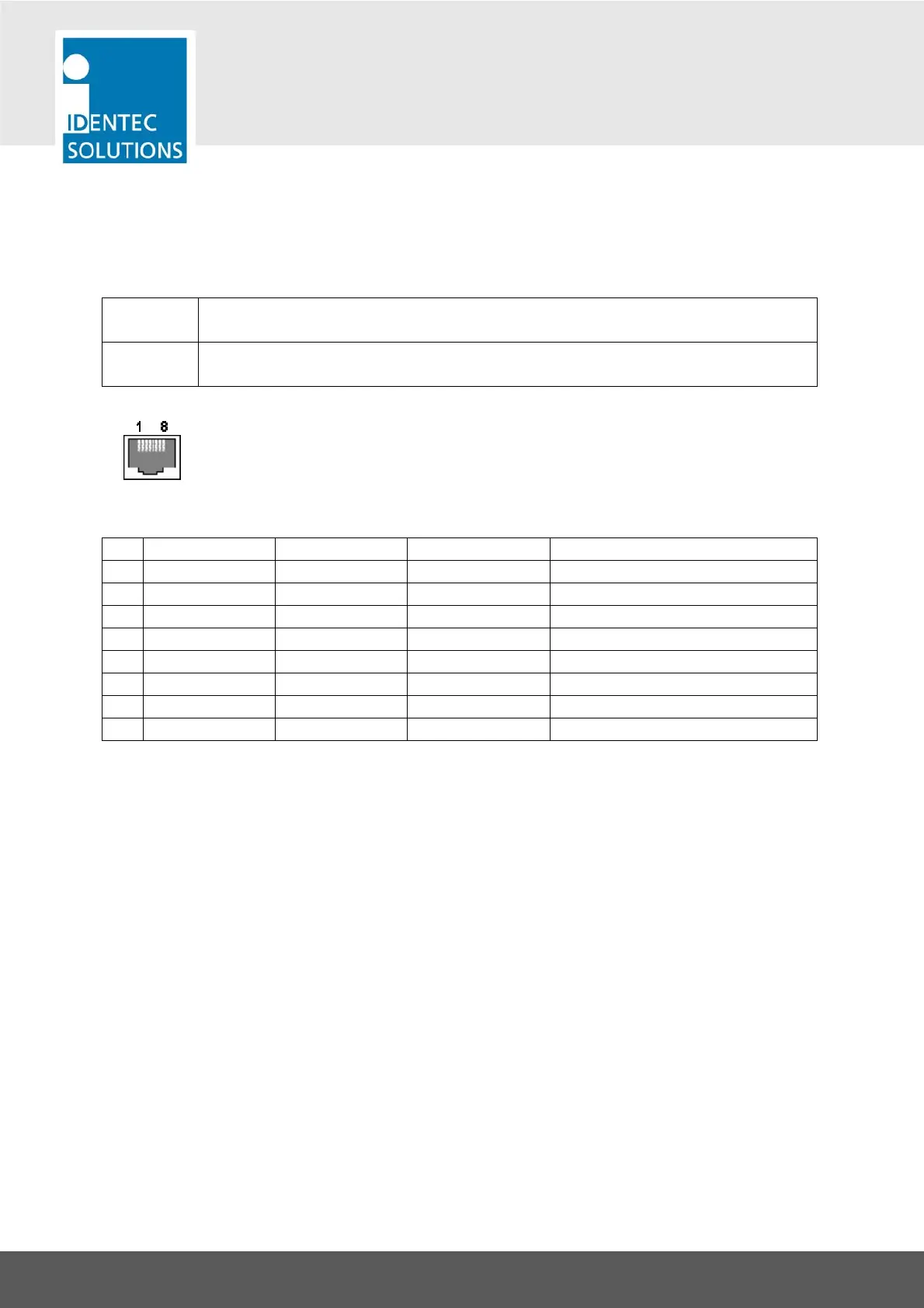
View into the connector = crimp/solder side of plug
Pin To Master To Slave T568B color Description
1 RxD+ TxD+ White/orange
2 RxD– TxD– Orange
3 TxD+ RxD+ White/Green
4 V+ (10 … 30V) V+ (10 … 30V) Blue Power supply for i-PORTs over bus
5 V+ (10 … 30V) V+ (10 … 30V) White/Blue Power supply for i-PORTs over bus
6 TxD– RxD– Green
7 GND GND White/Brown Power supply for i-PORTs over bus
8 GND GND Brown Power supply for i-PORTs over bus
As the TxD/RxD crossing is done by the pinout of the connectors, simple straight cabling has to be
used.
Connection parameters
Signal levels: RS422
Baud rate: 115200 bits per second
Data bits: 8
Stop bits: 1
Parity: none
Mode: half duplex
Flow Control: none