i-MARK 2 / i-MARK 3
USER MANUAL
VISIBILITY DELIVERED. PAGE 45 OF 55
8.5 Example Configurations
Marker Loops at Gates
Several loops in close proximity to each other
All i-MARKs connected via i-BUS
Tags pass through marker loops, they don’t remain in them
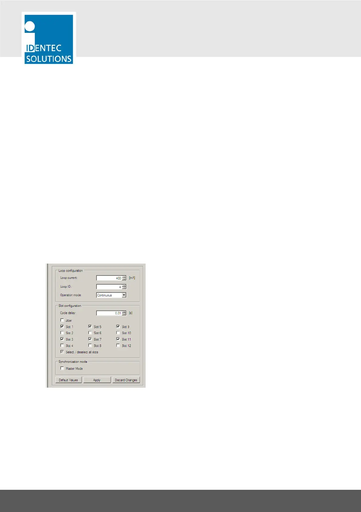
The standard setting will be:
Adjust the size of the inductive loop field with the loop current
Give every i-MARK a unique Loop ID
Leave Operation mode to “Continuous”
Set transmission slots unique for each loop in proximity
Set only the first device on the i-BUS to Master Mode
The example shows a setting for 2 adjacent marker loops. This i-MARK is set to use only the odd slot
numbers. The second loop is be set to use the even slot number.