i-MARK 2 / i-MARK 3
USER MANUAL
VISIBILITY DELIVERED. PAGE 40 OF 55
7.2.7 Maximum Overall Cable Runs of i-BUS
There are 2 general limitations on the length of the i-BUS cabling:
The overall length of the i-BUS over all units on the BUS must not exceed 1000 m (3000 ft)
The distance from one unit to the next on the i-BUS must not exceed 300 m (1000 ft)
Mixed operation of i-MARKs and i-PORTs on one i-BUS
While i-PORTs can potentially be supplied over the i-BUS, the i-MARK’s power consumption is too
high. So every i-MARK2/3 needs to have a local power supply.
So with i-PORTs powered via the i-BUS, the voltage drop over the wiring also needs to be taken into
account. The following table gives a recommendation of the overall length of an i-BUS with i-PORTs
powered over the i-BUS.
This table is valid for Cat5 cabling with gauge diameters of AWG24. The maximum distance between
any two units (i-MARK types and i-PORT types) is limited to 300 m (approx. 1000 ft).
# of i-PORTs Length (m/ft) Remark
1 300/1000 One 24V
2 600/2000 One 24V
3 400/1300 One 24V
4 250/820 One 24V
5 200/650 One 24V
8 100/300 One 24V
8 1000/3000 GND potential free power supplies at every i-PORT M
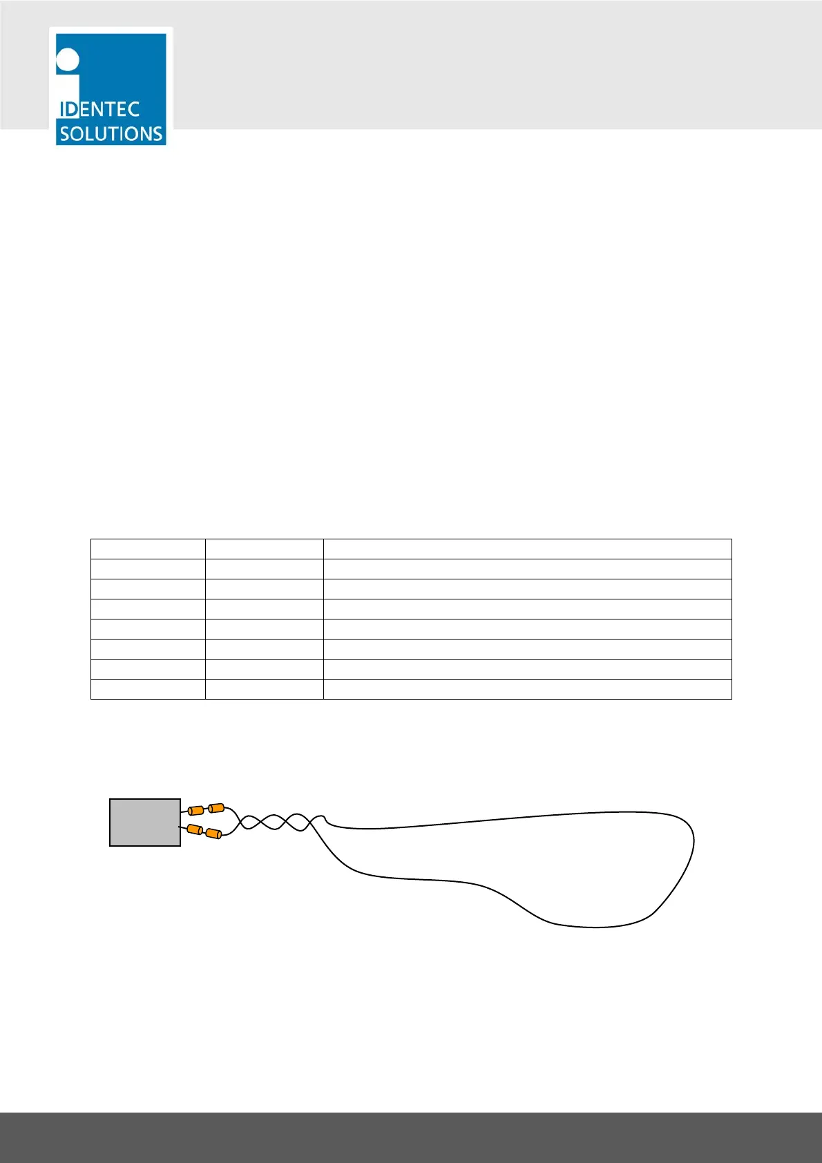
7.2.8 The External Marker Loop (i-MARK 3 only)
Ferrite rings are included in the delivery of an i-MARK 3.
i-MARK 3
Marker Loop
In the US:
Place 2 ferrite rings around every cable of the
marker loop. The ferrite rings should be as close
as possible to the housing of the i-MARK.