13
DOC No: 8540 REV D
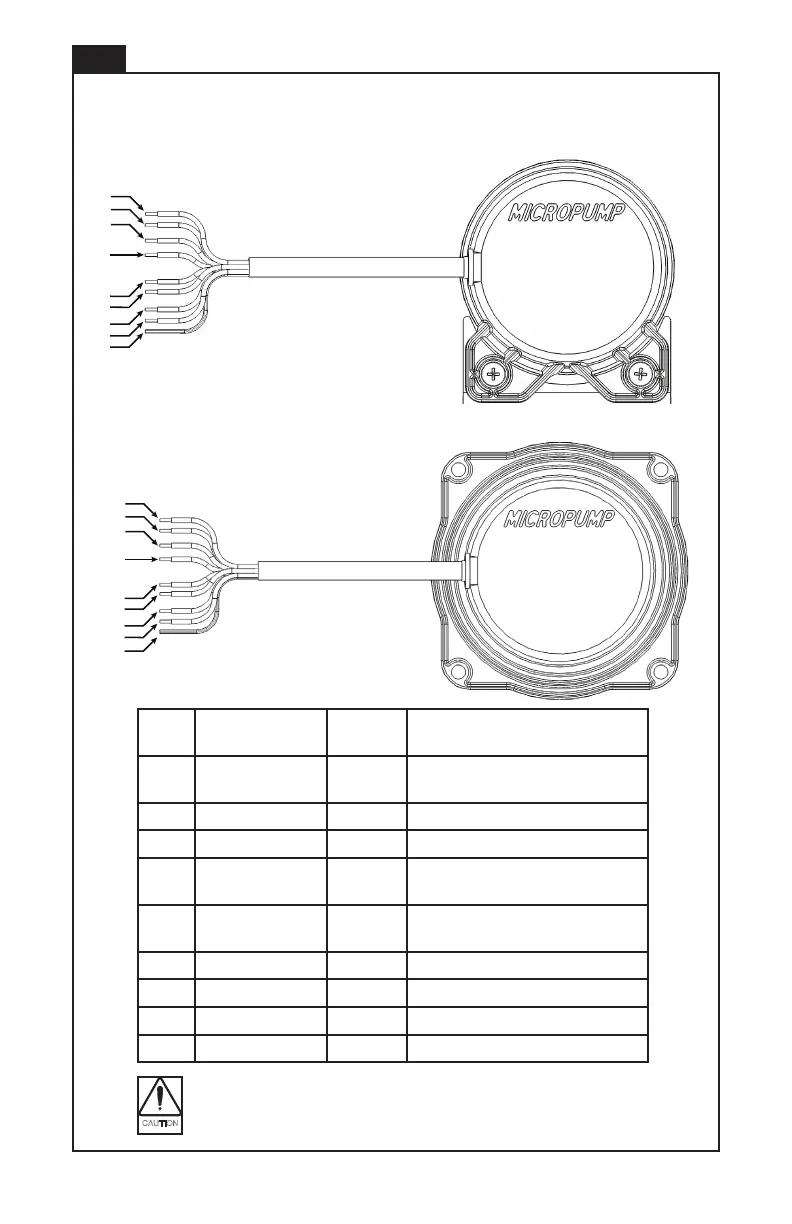
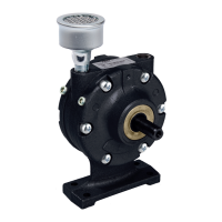
MODEL MS
1
2
3
4
5
7
8
9
6
1
2
3
4
5
7
8
9
6
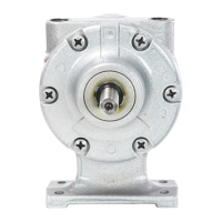
MODEL EL
Lead Function Color
1 Power In Red +12 to +36 VDC, Class 2 (SELV),
Reverse-polarity protected
2 Common Black Isolated from motor housing
3 Control Signal In Yellow 0-5 VDC
4 Tachometer Out Green 5 V square wave-2 pulses per
revolution
5 FWD/REV Orange Forward (oat and insulate), Reverse
(ground)
qww Not Connected Violet None
7 Error Out Blue Fault Signal 2
8 Error Out Brown Fault Signal 1
9 Shield - Connected to Common
EagleDrive Lead Wire Assignments
The 0-5 VDC Control Signal In must be within -0.3 to +5.1 VDC or the
motor will be irrepairably damaged.