8A3xxxx 144BGA EVK User Manual
© 2019 Integrated Device Technology, Inc.
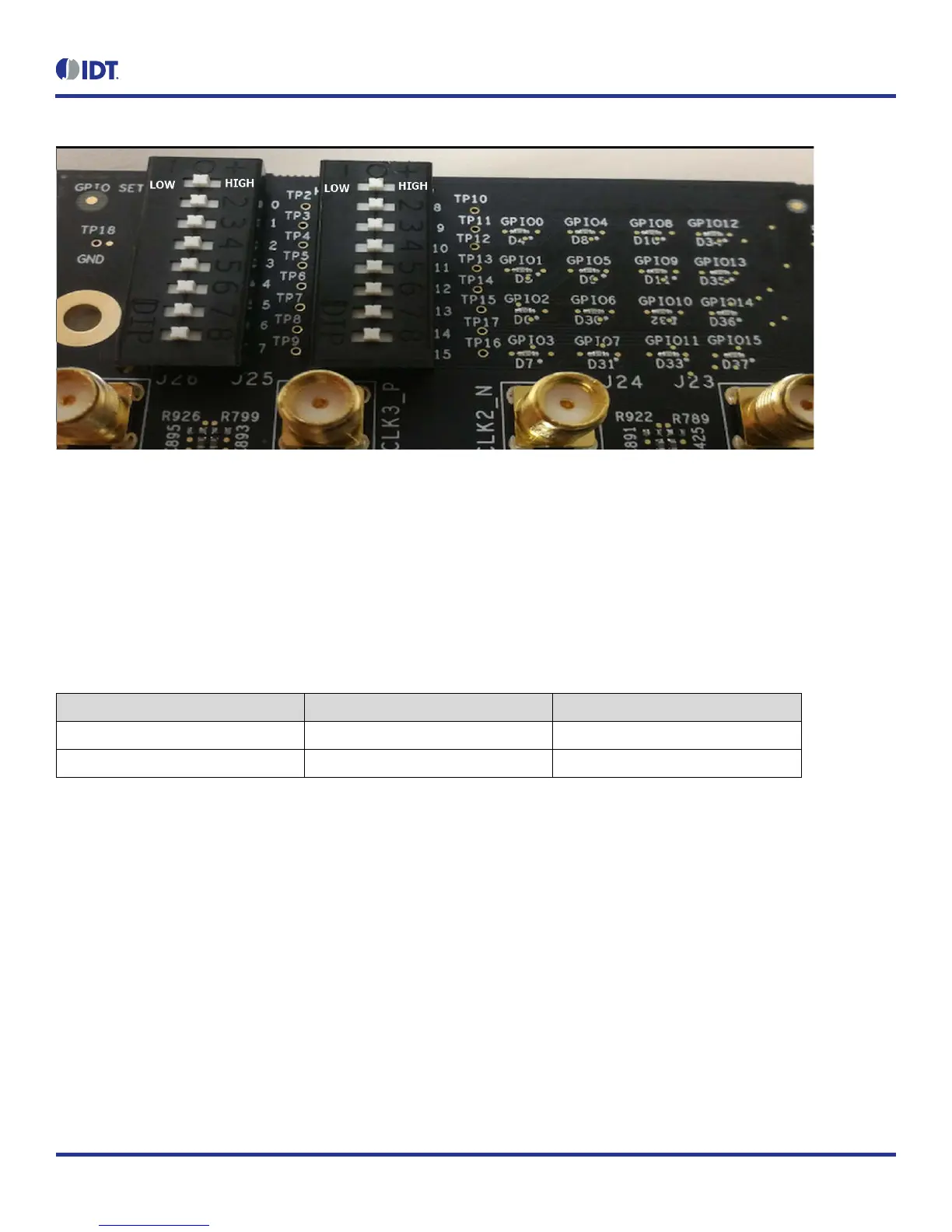
Figure 3. GPIO Setting and Status Display Area
1.5 USB Jack
The board has a USB mini-connector. The other end of the USB cable is a USB Type A connector going to a PC.
1.6 Onboard EEPROM
An onboard EEPROM is used to store device firmware and/or customer’s configuration data. There are two headers/jumpers, JP10 and JP11,
used to select the I
2
C communication paths for the EEPROM.
Table 2. EEPROM I
2
C Connections
JP10/JP11 JP10/JP11
Jumper Position Both Pin 1 and 2 Both Pin 2 and 3
EEPROM I
2
C Path FDTI and EEPROM EEPROM and CM Chip
 Loading...