8A3xxxx 144BGA EVK User Manual
© 2019 Integrated Device Technology, Inc.
2. Working with Timing Commander™ for Programing/Configuration
The following sections are best cross-referenced with the ClockMatrix GUI Step-by-Step User Guide which is available on www.idt.com.
2.1 Default Operation
The board can operate off an EEPROM that has stored all information including firmware and a default configuration data. A default operation
provides a sanity check on the board before running the board through the IDT Timing Commander. Please set the board in the following default
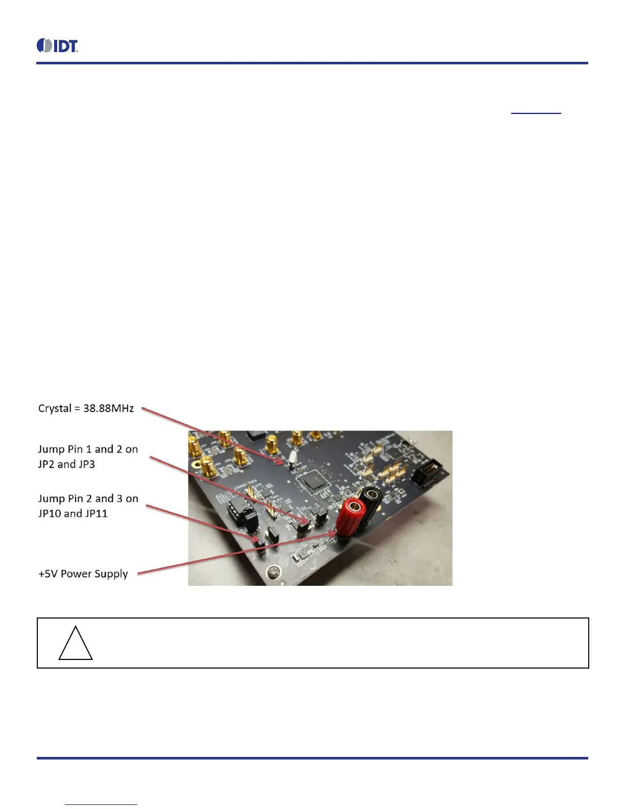
conditions (see Figure 4 for jumper and switch positions).
• Set all the GPIOs to the center position. This will ensure that GPIO8 and GPIO9 are high and that the serial port is configured for I
2
C
1-byte addressing.
• VDDA = 3.3V, VCC_GPIO_DC = 3.3V, and VDDO_Qx = 3.3V
• Crystal frequency = 50MHz
• CLK0 = 25MHz
• EEPROM is connected to ClockMatrix chip through an I
2
C bus by jumping Pin 2 and 3 of JP10 and JP11
With the above default conditions ready, connect the board to the PC using a USB type A to USB mini cable, and power up the board using a
single +5V supply. On power-up, the ClockMatrix chip will read its firmware and configuration data from EEPROM and update all registers.
When this process is completed, the following frequencies are available:
Q0 = 122.88MHz
Q1 = 122.88MHz
Figure 4. Board Setting for Default Operation
Important Equipment Warning: In order to set GPIO8 and GPIO9 to “High”, the switches for GPIO8 and GPIO9
must be set either to the “+” (high) position or the center position.
 Loading...