Quick Installation Guide
Jun. 2011 Copyright © IDTECK Co., Ltd.
(5) Now, the Main Unit is entered into the normal operation mode with factory defaulted settings.
7.4. Registration of RF/PIN Combination MODE
(1) Apply 12V DC to the unit.
All 3 LEDs will be flashing with a power-up melody.
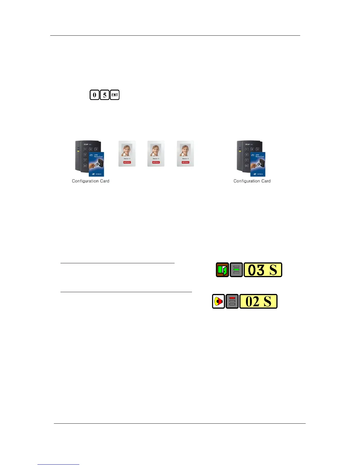
(2) Press from the keypad. (RF/PIN Combination Mode)
(3) Present Configuration Card to register Configuration Card to the unit.
(4) Present RF Card or enter 4~6 digit PIN number to register user access card or PIN.
(5) Present Configuration Card to complete the registration
. . . . .
or or or
PIN PIN PIN
7.5. Factory Defaulted Setting Values
After the Initial Setup, the Main Unit uses the factory defaulted setting values below to execute the
normal operation mode. You may want to change these factory setting values or modify your User
Access list; refer to section 12 of the main manual for instructions on how to customize the
operation of your unit.
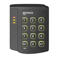
(1) When User Access Card (or PIN) is granted
- Door RELAY activates for 3sec.
- Green LED lights on for 3sec.
(2) When User Access Card (or PIN) is not recognized
- Alarm RELAY activates for 2sec.
- Red LED lights on for 2sec.
(3) Duress Password = 00, Duress Alarm to TTL output port for 03 sec.
(4) QUICK ACCESS MODE = Disable
(5) Chime Bell output = Enable, Chime Bell activation time = 05 sec.
(6) Melody sound = Enable
(7) Keypad lock-out time when Try-Out error detected = 01 min.
(8) Detect all inputs from ‘H’ to ‘L’
(9) Activate TTL output to ‘L’
(10) Delay time to activate SECURE MODE = 00 min.
(11) Door Open time-out for Door Contact sensor = 00 sec.
(12) Number of times of Try-out = 05 times
(13) Input keypress time-out time = 20 sec.