5.6 Wiring an Accessory Relay Board
(242eM only)
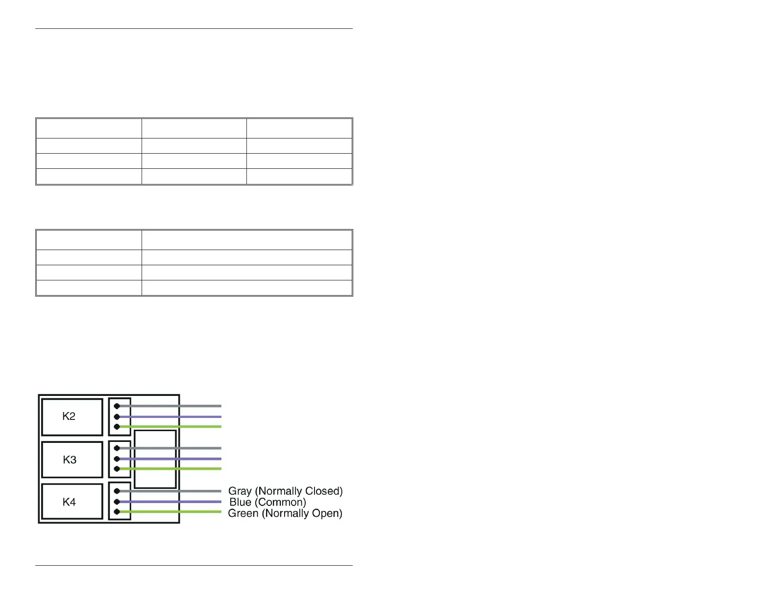
Theaccessoryrelayboardcontainsphysicaloutputs2,3,and4
shown in the table below.
Physical Output Relay Connector
2K2P1
3K3P2
4K4P3
Use the wire harnesses supplied with the relay board to connect to
therelays.Thewirecolorsareshowninthetablebelow.
Wire Color Relay Connection
Gray Normally Closed
Blue Common
Green Normally Open
5.7 Wiring an Integrated Access Control
System Using the Accessory Relay Board
Physicaloutputs2,3,and4aredefaulted to the alarm shunt,
propped door, and forced door virtual outputs, respectively. Use the
following steps to wire the alarm shunt, propped door alarm, and
forced door alarm.
Figure 9 Wiring an Accessory Relay Board
IEI 212eM/242eM Standalone Installation/Programming Manual
12 Document # 6174000, Rev. 1.1
 Loading...