5. Wiring
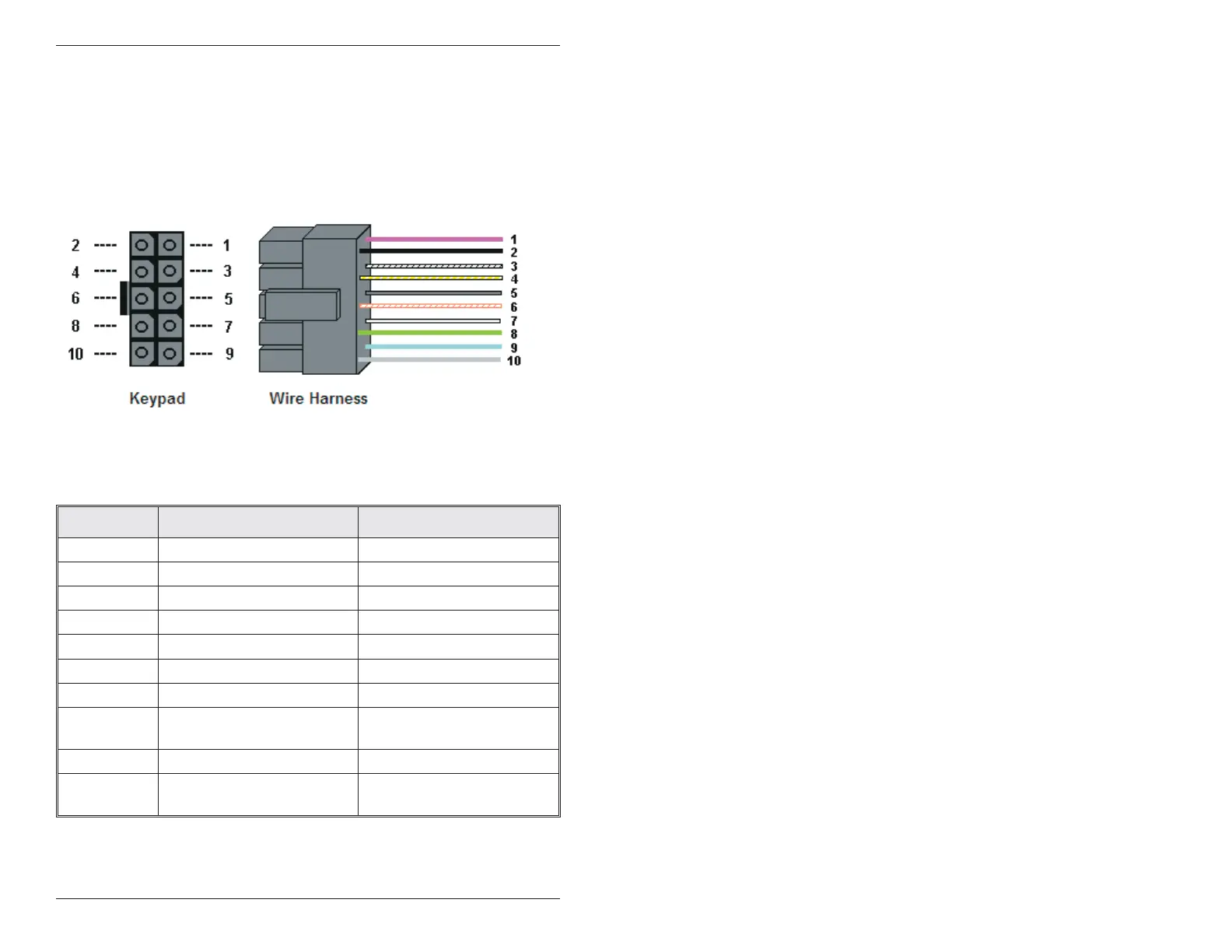
5.1 Wire Harness Configuration
Pin Wire Color Signal Name
1 Red V+ (Keypad Power)
2 Black V- (Keypad Power)
3 White/Black Not Used
4 White/Yellow Not Used
5 Brown Remote Trigger (REX)
6 White/Orange Loop Common
7 White Door Loop Monitor
8 Green
Main Relay - Normally
Open
9 Blue Main Relay - Common
10 Gray
Main Relay - Normally
Closed
Figure 4 Keypad Connector and Wire Harness
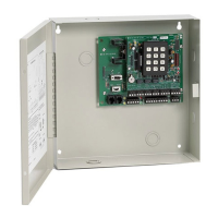
NOTE: For wiring the accessory relay board, see sections 5.6 and
5.7.
IEI 212eM/242eM Standalone Installation/Programming Manual
8 Document # 6174000, Rev. 1.1
 Loading...