Do you have a question about the IEMCA BOSS 338 HD and is the answer not in the manual?
Details the warranty period conditions and requirements for product validity.
Explains the manual's objective, contents, and the meaning of symbols used.
Lists the identification plate details required for information and ordering.
Provides guidance on how to request technical assistance.
Lists the documents supplied with the bar feeder manual.
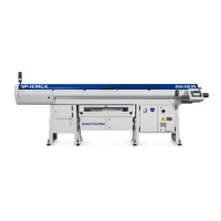
Provides an overview of the BOSS automatic bar feeder and its applications.
Details the sequence of movements controlled by the PLC during operation.
Describes the various safety devices installed on the bar feeder.
Illustrates the location and meaning of safety plates on the equipment.
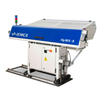
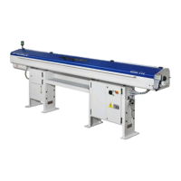
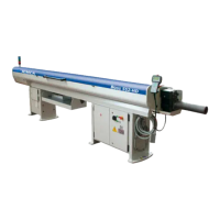
Details the different models and their specifications, like magazine length.
Presents technical specifications, dimensions, and capacities of the bar feeder.
Outlines essential safety rules for operating and maintaining the bar feeder.
Specifies safety precautions during handling, installation, and electrical connection.
Details safety measures to be followed during adjustments and setup procedures.
Provides safety guidelines for the proper use and operation of the bar feeder.
Highlights safety precautions for performing maintenance operations.
Contains the manufacturer's declaration of compliance with EC regulations.
Describes the bar feeder as an interchangeable equipment with safety devices.
Identifies potential residual risks associated with pneumatic, electric, and mechanical systems.
Lists common improper uses and potential hazards to avoid during operation.
Describes the different packaging options for the bar feeder.
Provides safety warnings and instructions for handling and lifting operations.
Specifies requirements for the installation area, including floor stability and ventilation.
Detailed steps for installing the bar feeder without the axial displacement feature.
Detailed steps for installing the bar feeder with the axial displacement feature.
Instructions for installing devices for coupling with sliding headstock lathes.
Instructions for installing devices for coupling with cam lathes.
Procedure for filling the lubricating oil tank and checking the level.
Safety warnings and instructions for connecting the bar feeder electrically.
Guidelines for connecting the pneumatic supply and adjusting air pressure.
Guidance on correctly parameterizing the bar feeder software.
Introduction to adjustments and setup operations for the bar feeder's service life.
Details necessary adjustments for correct operation, maintenance, and troubleshooting.
Procedures for setting up the bar feeder based on new bar diameter and machining type.
Explains the timing procedure for the cam box and microswitch functions.
Overview of control functionalities and manual/automatic mode operations.
Detailed description of the handheld keyboard functions and buttons.
Explains the meaning of the light indicators for different operational states.
Guidelines for selecting and preparing bars for machining operations.
Sequence of operations for initial setup and starting the automatic cycle.
Instructions for stopping the bar feeder during normal operation or emergencies.
Procedure to restart the automatic cycle after manual operations.
Steps to resume operation after a power interruption.
A quick guide for changing machining types, including guide channel changes.
General principles and safety rules for cleaning and maintaining the bar feeder.
Provides a table outlining scheduled maintenance tasks and their frequencies.
Instructions on how to use the axial displacement device for maintenance access.
Lists common general failures, their causes, and solutions.
Troubleshooting guide for issues related to the bar magazine.
Addresses problems encountered during the feeding process into the collet.
Troubleshooting common failures related to the bar feeding mechanism.
Information on replacing the feeding chain, directing to service department.
Procedure for replacing the guide channel opening belt.
Instructions for replacing guide channels with inserts and polyurethane ones.
Lists recommended spare parts subject to wear or breakage.
Guidelines for machine dismantling and proper disposal of components.
Table detailing guide channels and bar pusher choices based on bar diameter.
Table for selecting revolving tips based on guide channel and bar pusher diameters.
Specifications and codes for revolving tips with ØGR 10-27mm.
Specifications and codes for revolving tips with ØGR 12-27mm.
Specifications and codes for revolving tips with ØGR 30-51mm.
Specifications and codes for revolving tips with ØGR 30-51mm.
Provides conversion tables for bar diameters.
Table for selecting steel collets based on hexagonal bar dimensions.
Table for selecting steel collets based on square bar dimensions.
Table for selecting steel collets based on hexagonal bar dimensions in inches.
Table for selecting steel collets based on round bar dimensions in inches.
Provides a conversion table between inches and millimetres.
Specifications for ejectors used with guide channels smaller than Ø30mm.
Specifications for ejectors used with guide channels larger than Ø32mm.
Information and code structure for pipe collets 012-077-377.
Table detailing dimensions and codes for pipe collets.
Information on collets for bars, model 011.
Table listing collets for bars and their specifications.
Information on boring collets for bars, model 601P.
Table for boring collets for square and hexagonal bars.
Information on collets for bars, model 602P.
Table listing collets for bars and their specifications.
Information on ejector model 602P..011.
Specifications for ejectors used with guide channels Ø13-28mm.
Table detailing dimensions and codes for pipe collets.
Table listing collets for bars and their specifications.
Table listing collets for bars and their specifications.
Specifications for 381P..021 ejectors with guide channels Ø33-46mm.
Specifications for 381P..011 ejectors with guide channels Ø52-86mm.
Table listing rings for collets and their part numbers.
| Type | Bar Feeder |
|---|---|
| Model | BOSS 338 HD |
| Maximum Bar Diameter | 38 mm |
| Remnant management | Automatic |
| Control system | IEMCA CNC |
| Bar stock shape | Round |
| Power Supply | 400 V, 50 Hz |