Do you have a question about the IEMCA MASTER865 VERSO MP SIII and is the answer not in the manual?
Details the terms and conditions for the product warranty.
Explains the objective and scope of this technical manual.
Information about the manufacturer and identification of the bar feeder.
Guidelines for requesting technical assistance and support.
Definitions of key terms used throughout the manual.
List of accompanying documents and materials provided with the bar feeder.
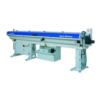
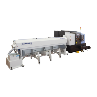
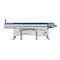
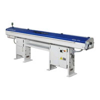
An overview of the automatic bar feeder's functionality and design.
Identifies and describes the primary components of the bar feeder.
Details the main components of the bar feeder's hydraulic system.
Details the main components of the bar feeder's pneumatic system.
Describes the sequence of operations performed by the bar feeder.
Outlines the various safety devices integrated into the bar feeder.
Locates and explains the safety plates and warnings on the machine.
Information regarding different versions or models of the bar feeder.
Provides detailed technical specifications and data for the bar feeder.
Information on the noise levels generated by the bar feeder during operation.
Introduction to optional accessories available for the bar feeder.
Description of the bush holder accessory and its function.
Fundamental safety rules and guidelines for operating the bar feeder.
Safety precautions during the handling and installation of the bar feeder.
Safety considerations for adjusting and setting up the bar feeder.
Safety practices for the daily use and operation of the bar feeder.
Safety procedures to follow during maintenance of the bar feeder.
Declaration of conformity with European Community directives.
Overview of what is included with the bar feeder supply.
Identification and explanation of residual risks associated with the machine.
Lists potential misuse scenarios and their associated dangers.
Information on the different packaging methods for the bar feeder.
Guidelines and precautions for safely lifting the bar feeder.
Procedures for lifting the bar feeder when it is not in its original packaging.
Procedures for lifting the bar feeder when it is on a pallet.
Procedures for lifting the bar feeder when it is in a crate.
Requirements and features of the area designated for bar feeder installation.
Preliminary information and considerations before installing the bar feeder.
Instructions for installing backing plates and support feet.
Steps for adjusting the working axis height of the bar feeder.
Guidance on the initial positioning of the bar feeder relative to the lathe.
Instructions for installing the sleeve component of the bar feeder.
Procedures for levelling and aligning the bar feeder with the lathe.
Steps for securely fastening the bar feeder to the ground or structure.
Instructions for filling the lubrication oil tank.
Details on how to make the electrical connections for the bar feeder.
Diagram and explanation of the pneumatic system layout.
Steps for connecting the pneumatic system of the bar feeder.
How to manually move bar feeder components when power is off.
Instructions for parameterizing the bar feeder's software.
Preliminary information for adjusting and setting up the bar feeder.
Introduction to general adjustments needed for bar feeder operation.
Procedure for adjusting the feeding chain of the bar feeder.
How to adjust the pressure switch.
Steps for setting up the bar feeder for specific operations.
Replacing guide channels, half bushes, bar pusher, and collet.
Step-by-step procedure for replacing the bar pusher.
How to adjust the bar selectors.
Description of the bar feeder's control system and interface.
Detailed explanation of the keyboard controls and their functions.
Explains the meaning of various light indicators on the bar feeder.
Steps and procedures for setting up the bar feeder for operation.
Requirements and preparation steps for bars to be machined.
Method for measuring and checking the straightness of bars.
Procedure for loading bars into the bar feeder magazine.
Steps to initiate the automatic operating cycle of the bar feeder.
Step-by-step guide for loading bars into the feeder.
How to adjust the flow rate of the lubricating oil.
Procedures for stopping the bar feeder, including emergency stops.
Explanation of the step-by-step operation mode.
General rules and guidelines for performing maintenance on the bar feeder.
Recommended maintenance schedule and tasks.
How to check the lubricating oil level.
Procedure for changing the lubricating oil.
How to check and maintain the air filter unit.
Diagram showing lubrication points and intervals.
Common problems, their causes, and solutions for the bar feeder.
Troubleshooting issues related to feeding bars into the collet.
Troubleshooting issues encountered during bar feeding.
Instructions for replacing the feeding chain component.
Procedure for replacing guide channels with polyurethane ones.
Steps to disassemble the insert guide channels.
Instructions for assembling polyurethane guide channels.
Replacing guide channels for different bar diameters.
Replacing guide channels when they fail or are damaged.
How to replace the PLC battery.
List of recommended spare parts for the bar feeder.
Guidelines for safely disposing of the bar feeder or its components.
Information on guide channels and bar pushers for the bar feeder.
Table listing revolving tips based on specifications.
Table of revolving tips for øGR 20-25 mm.
Another table for revolving tips for øGR 20-25 mm.
Table of revolving tips for øGR 32-45 mm.
Table of revolving tips for øGR 51-70 mm.
Conversion tables for various measurements.
Table for hexagonal bar dimensions in millimeters.
Table for square bar dimensions in millimeters.
Table for hexagonal bar dimensions in inches.
Table for round bar dimensions in inches.
Conversion table between inches and millimeters.
Specific collets for 011 bars.
General table for collets used with bars.
Information on pipe collets 012-077-377.
Table listing pipe collets.
Details about ejector 336.
Table for ejectors for guide channels with diameter less than 30 mm.
Table for ejectors for guide channels with diameter greater than 32 mm.
Specific collets for bars, model 602P.
General table for collets used with bars, model 602P.
Boring collets for bars, model 601P.
Table for boring collets for square and hexagonal bars.
Information on ejectors 602P..011.
Table for ejectors for guide channels with diameter 13-28 mm.
Information on pipe collets 603P.
Table listing pipe collets, model 603P.
Specific collets for bars, model 076.
General table for collets used with bars, model 076.
Specific collets for bars, model 381P.
General table for collets used with bars, model 381P.
Information on ejectors 381P..011 - 381P..021.
Table for ejectors 381P..021 for guide channels 33-46 mm.
Table for ejectors 381P..011 for guide channels 52-71 mm.
Information on pipe collets 386P.
Table listing pipe collets, model 386P.
Rings for collets 078-225.
Table listing rings for collets.
| Type | Bar Feeder |
|---|---|
| Model | MASTER865 VERSO MP SIII |
| Bar diameter capacity | 8 - 65 mm |
| Maximum bar diameter | 65 mm |
| Minimum bar diameter | 8 mm |
| Compressed air requirement | 6 bar |
| Power supply | 400V |