7
UK
4.2 Communication, parameter setting, evaluation
OUT1 (pin 4)
• Switching signal for system pressure limit
• Communication via IO-Link
OUT2 (pin 2)
• Switching signal for system pressure limit
• Analogue signal 4���20 mA / 0���10 V
4.3 Switching function
OUTx changes its switching status if it is above or below the set switching limits
(SPx, rPx)� The following switching functions can be selected:
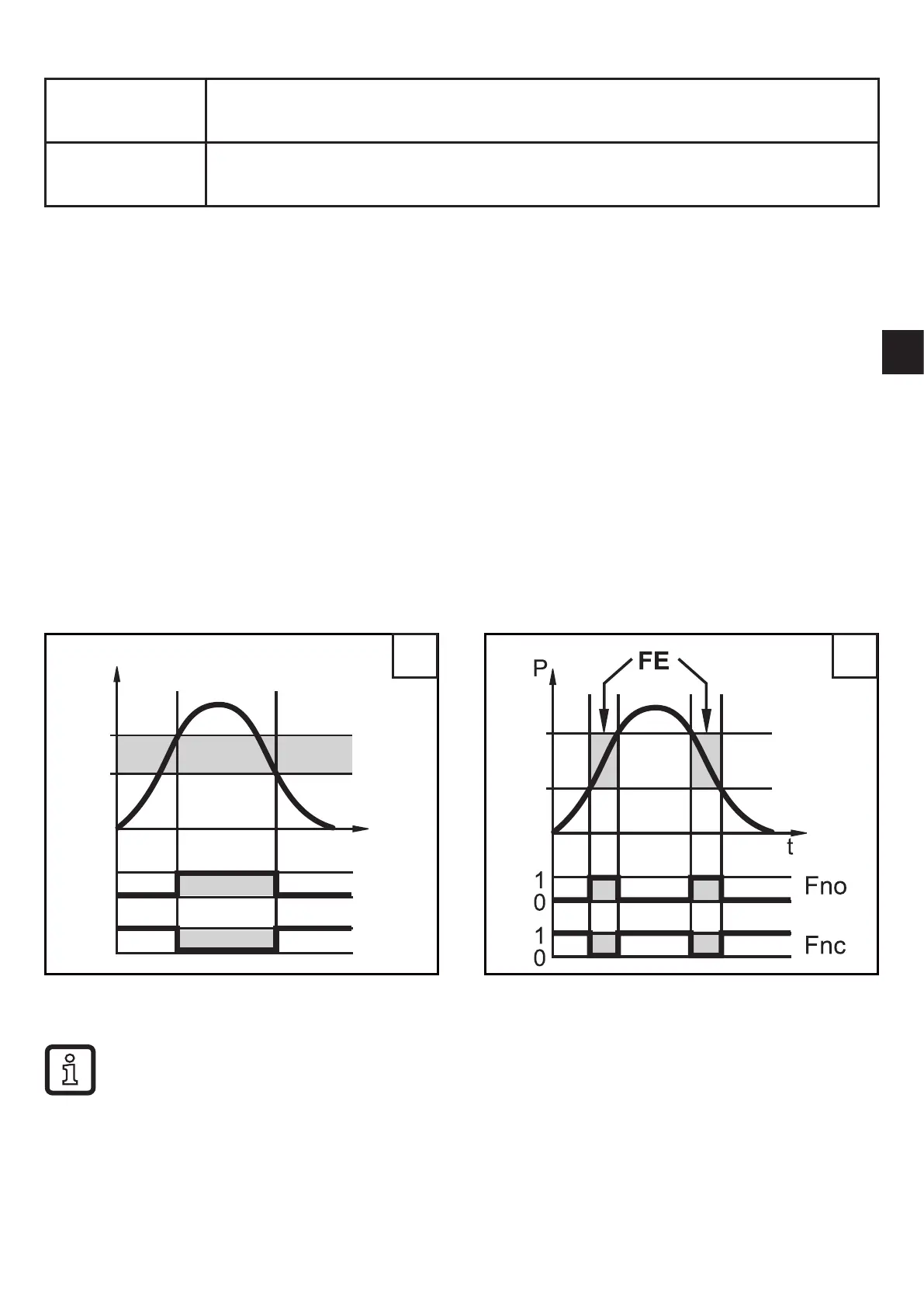
• Hysteresis function / normally open: [ou1/ou2] = [Hno] (→ Fig. 1).
• Hysteresis function / normally closed: [ou1/ou2] = [Hnc] (→ Fig. 1).
First the set point (SPx) is set, then the reset point (rPx)�
The hysteresis defined remains even if SPx is changed again�
• Window function / normally open: [ou1/ou2] = [Fno] (→ Fig. 2).
• Window function / normally closed: [ou1/ou2] = [Fnc] (→ Fig. 2).
The width of the window can be set by means of the difference between FHx
and FLx� FHx = upper value, FLx = lower value�
FH
FL
1 2
P = system pressure; HY = hysteresis; FE = window
When set to the window function the set and reset points have a fixed
hysteresis of 0�25 % of the measuring span�
 Loading...