6
4 Installation
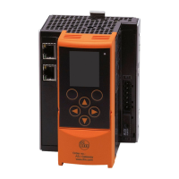
► Fix the AS-i Profinet gateway onto a 35 mm DIN rail�
The protection rating of the unit is IP 20, therefore it should be mounted in a
protected location (e�g� control cabinet)�
Ensure a condensation-free environment� Avoid excessive dust, vibration
and shock� The air circulation through the vents must not be impeded�
Avoid installation in direct vicinity of frequency inverters or other interfering
sources�
5 Electrical connection
The device must be connected by a qualified electrician�
► Disconnect power before connecting the device�
► Observe the national and international regulations for the installation of
electrical equipment�
► Connect the device as indicated on the terminals�
► Ensure an electrical connection between the AS-i Profinet gateway
(terminal FE) and the ground of the installation�
► Only insert or remove the AUX jumper when the device is disconnected�
Otherwise, a device failure may occur�
5.1 Device supply
To operate an AS-i system, an AS-i power supply (e�g� AC1236) or the
data decoupling module AC1250 (not supplied) with a DC power supply is
required�
► Supply the device with one of the following versions�
5.1.1 Device supply via AUX, AS-i supply via AS-i power supply
► Supply the device with a voltage of 24 V DC (18���32 V PELV) (e�g� from the
24 V DN3011 power supply of ifm electronic)� The connection is made to the
terminals X2�
► Pull out the AUX jumper�
► To supply the AS-i lines, connect the terminals X1 to one or two AS-i power
supplies (AC1401: one AS-i master, AC1402: two AS-i masters)�