7
UK
► Ensure a low-resistance connection of the symmetry point of the device
(terminal X1�5 FE) to the ground of the installation�
5.1.2 Device and AS-i supply via the AS-i power supply
► To supply the AS-i lines connect the terminals X1 to one or two AS-i power
supplies (AC1401: one AS-i master, AC1402: two AS-i masters)�
► Ensure a low-resistance connection of the symmetry point of the device
(terminal X1�5 FE) to the ground of the installation�
The AUX jumper is plugged onto the connector X2 (factory setting), the
device is supplied via AS-i line 1 (x1�3 and S1�4)�
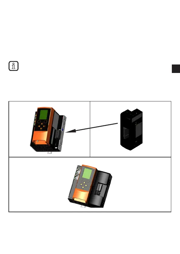
5.1.3 Device and AS-i supply via one common power supply
► Plug the data decoupling module AC1250 (not supplied) into the terminals X1
and X2 to supply the device and the connected AS-i lines�
► Ensure a low-resistance connection of the data decoupling (terminal „FE“) to
the ground of the installation�
The gateway and both AS-i lines are supplied via one power supply (PELV
21�5 V���31�6 V AS-i or AUX)� The AS-i lines have a thermal short-circuit protection
(4A)�