Do you have a question about the IFM LMT 0 Series and is the answer not in the manual?
Explains symbols used in the manual for instructions, reactions, designations, and important notes.
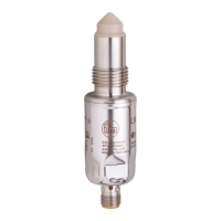
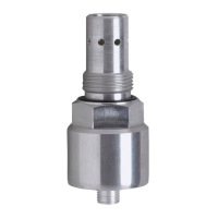
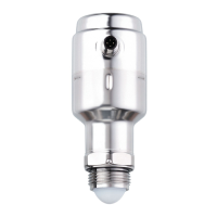
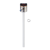
Lists key applications, media compatibility, and process connections for different unit types.
Details the impedance spectroscopy method used by the sensor to evaluate media electrical behaviour.
Highlights features like streamlined geometry, orientation-independent installation, and cable entry positioning.
Illustrates practical uses of the sensor, including tank and pipe monitoring with different probe types.
Provides guidelines on preferred installation sites, sensor contact with process connections, and interference precautions.
Details the step-by-step process for installing sensors, including seal placement and tightening torque.
Information regarding 3A approval validity, limitations, and specific criteria for installation.
Details EHEDG certification validity, adapter requirements, and integration for hygienic applications.
Describes the IO-Link interface capabilities for data access, parameter setting, and configuration information.
Explains how to connect sensors to a PC via IO-Link for parameter setting and reading values.
Details using a memory plug to write, transfer, and save parameter sets for the unit.
Covers parameter adjustments made while the unit is operating, requiring an IO-Link master.
Lists and describes various parameters like set points, hysteresis, output functions, and delays.
Details activating the teach input for parameter setting, including hysteresis and window functions.
Describes the operating status, LED indicators, and output states (OUT1, OUT2) for different conditions.
| Brand | IFM |
|---|---|
| Model | LMT 0 Series |
| Category | Accessories |
| Language | English |